PDF Publication Title:
Text from PDF Page: 005
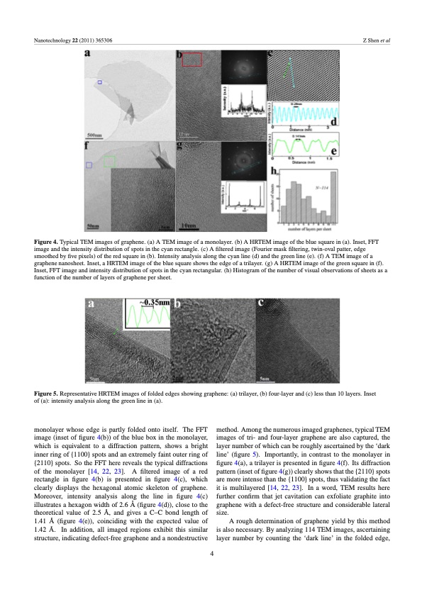
Nanotechnology 22 (2011) 365306 Z Shen et al Figure 4. Typical TEM images of graphene. (a) A TEM image of a monolayer. (b) A HRTEM image of the blue square in (a). Inset, FFT image and the intensity distribution of spots in the cyan rectangle. (c) A filtered image (Fourier mask filtering, twin-oval patter, edge smoothed by five pixels) of the red square in (b). Intensity analysis along the cyan line (d) and the green line (e). (f) A TEM image of a graphene nanosheet. Inset, a HRTEM image of the blue square shows the edge of a trilayer. (g) A HRTEM image of the green square in (f). Inset, FFT image and intensity distribution of spots in the cyan rectangular. (h) Histogram of the number of visual observations of sheets as a function of the number of layers of graphene per sheet. Figure 5. Representative HRTEM images of folded edges showing graphene: (a) trilayer, (b) four-layer and (c) less than 10 layers. Inset of (a): intensity analysis along the green line in (a). monolayer whose edge is partly folded onto itself. The FFT image (inset of figure 4(b)) of the blue box in the monolayer, which is equivalent to a diffraction pattern, shows a bright inner ring of {1100} spots and an extremely faint outer ring of {2110} spots. So the FFT here reveals the typical diffractions of the monolayer [14, 22, 23]. A filtered image of a red rectangle in figure 4(b) is presented in figure 4(c), which clearly displays the hexagonal atomic skeleton of graphene. Moreover, intensity analysis along the line in figure 4(c) illustrates a hexagon width of 2.6 A ̊ (figure 4(d)), close to the theoretical value of 2.5 A ̊ , and gives a C–C bond length of 1.41 A ̊ (figure 4(e)), coinciding with the expected value of 1.42 A ̊ . In addition, all imaged regions exhibit this similar structure, indicating defect-free graphene and a nondestructive method. Among the numerous imaged graphenes, typical TEM images of tri- and four-layer graphene are also captured, the layer number of which can be roughly ascertained by the ‘dark line’ (figure 5). Importantly, in contrast to the monolayer in figure 4(a), a trilayer is presented in figure 4(f). Its diffraction pattern (inset of figure 4(g)) clearly shows that the {2110} spots are more intense than the {1100} spots, thus validating the fact it is multilayered [14, 22, 23]. In a word, TEM results here further confirm that jet cavitation can exfoliate graphite into graphene with a defect-free structure and considerable lateral size. A rough determination of graphene yield by this method is also necessary. By analyzing 114 TEM images, ascertaining layer number by counting the ‘dark line’ in the folded edge, 4PDF Image | Preparation of graphene by jet cavitation
PDF Search Title:
Preparation of graphene by jet cavitationOriginal File Name Searched:
graphene-by-jet-cavitation.pdfDIY PDF Search: Google It | Yahoo | Bing
Salgenx Redox Flow Battery Technology: Power up your energy storage game with Salgenx Salt Water Battery. With its advanced technology, the flow battery provides reliable, scalable, and sustainable energy storage for utility-scale projects. Upgrade to a Salgenx flow battery today and take control of your energy future.
CONTACT TEL: 608-238-6001 Email: greg@infinityturbine.com (Standard Web Page)