Search Completed | Title | ORC Organic Rankine Cycle Power Systems Updates 2024
Original File Name Searched: af_orc_editorial.pdf | Google It | Yahoo | Bing
Page | 019 Paper ID: #3, Page 7
Paper ID #3, page 7 of 10
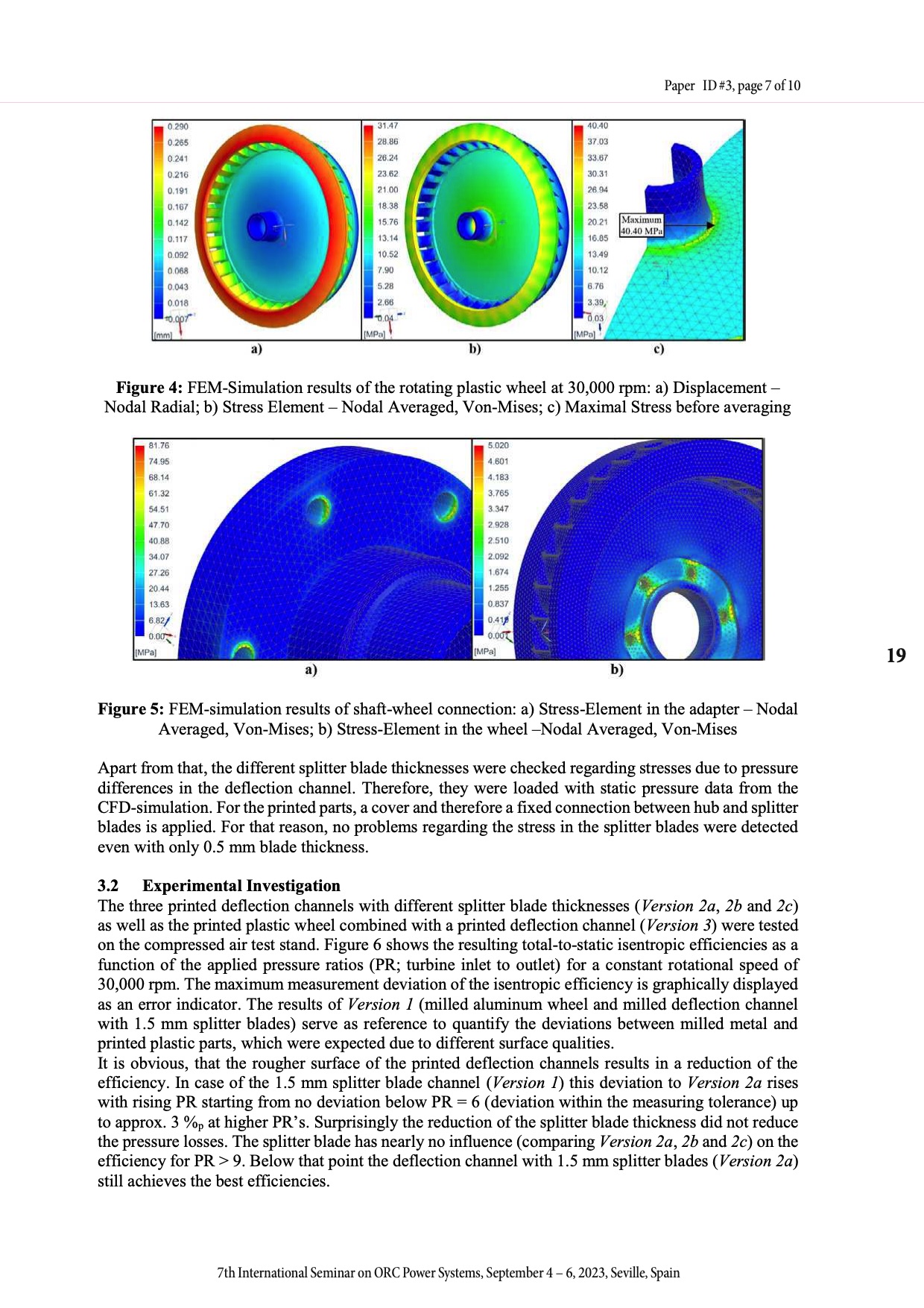
Figure 4: FEM-Simulation results of the rotating plastic wheel at 30,000 rpm: a) Displacement – Nodal Radial; b) Stress Element – Nodal Averaged, Von-Mises; c) Maximal Stress before averaging
Figure 5: FEM-simulation results of shaft-wheel connection: a) Stress-Element in the adapter – Nodal Averaged, Von-Mises; b) Stress-Element in the wheel –Nodal Averaged, Von-Mises
Apart from that, the different splitter blade thicknesses were checked regarding stresses due to pressure differences in the deflection channel. Therefore, they were loaded with static pressure data from the CFD-simulation. For the printed parts, a cover and therefore a fixed connection between hub and splitter blades is applied. For that reason, no problems regarding the stress in the splitter blades were detected even with only 0.5 mm blade thickness.
3.2 Experimental Investigation
The three printed deflection channels with different splitter blade thicknesses (Version 2a, 2b and 2c) as well as the printed plastic wheel combined with a printed deflection channel (Version 3) were tested on the compressed air test stand. Figure 6 shows the resulting total-to-static isentropic efficiencies as a function of the applied pressure ratios (PR; turbine inlet to outlet) for a constant rotational speed of 30,000 rpm. The maximum measurement deviation of the isentropic efficiency is graphically displayed as an error indicator. The results of Version 1 (milled aluminum wheel and milled deflection channel with 1.5 mm splitter blades) serve as reference to quantify the deviations between milled metal and printed plastic parts, which were expected due to different surface qualities.
It is obvious, that the rougher surface of the printed deflection channels results in a reduction of the efficiency. In case of the 1.5 mm splitter blade channel (Version 1) this deviation to Version 2a rises with rising PR starting from no deviation below PR = 6 (deviation within the measuring tolerance) up to approx. 3 %p at higher PR’s. Surprisingly the reduction of the splitter blade thickness did not reduce the pressure losses. The splitter blade has nearly no influence (comparing Version 2a, 2b and 2c) on the efficiency for PR > 9. Below that point the deflection channel with 1.5 mm splitter blades (Version 2a) still achieves the best efficiencies.
19
7th International Seminar on ORC Power Systems, September 4 - 6, 2023, Seville, Spain
7th International Seminar on ORC Power Systems, September 4 – 6, 2023, Seville, Spain
|