PDF Publication Title:
Text from PDF Page: 010
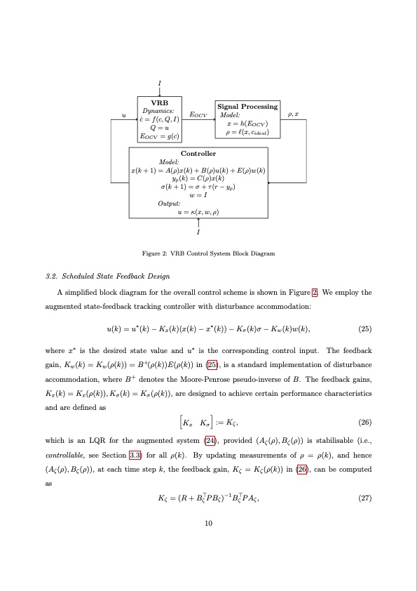
I u EOCV ρ,x VRB Dynamics: c ̇ = f(c,Q,I) Q=u EOCV = g(c) Signal Processing Model: x = h(EOCV ) ρ = l(x,cideal) Controller Model: x(k + 1) = A(ρ)x(k) + B(ρ)u(k) + E(ρ)w(k) yp(k) = C(ρ)x(k) σ(k + 1) = σ + τ(r − yp) w=I Output: u = κ(x,w,ρ) I Figure 2: VRB Control System Block Diagram 3.2. Scheduled State Feedback Design A simplified block diagram for the overall control scheme is shown in Figure 2. We employ the augmented state-feedback tracking controller with disturbance accommodation: u(k) = u∗(k) − Kx(k)(x(k) − x∗(k)) − Kσ(k)σ − Kw(k)w(k), (25) where x∗ is the desired state value and u∗ is the corresponding control input. The feedback gain, Kw(k) = Kw(ρ(k)) = B+(ρ(k))E(ρ(k)) in (25), is a standard implementation of disturbance accommodation, where B+ denotes the Moore-Penrose pseudo-inverse of B. The feedback gains, Kx(k) = Kx(ρ(k)),Kσ(k) = Kσ(ρ(k)), are designed to achieve certain performance characteristics and are defined as K K :=Kζ, (26) xσ which is an LQR for the augmented system (24), provided (Aζ(ρ),Bζ(ρ)) is stabilisable (i.e., controllable, see Section 3.3) for all ρ(k). By updating measurements of ρ = ρ(k), and hence (Aζ(ρ),Bζ(ρ)), at each time step k, the feedback gain, Kζ = Kζ(ρ(k)) in (26), can be computed as ⊤ −1⊤ Kζ =(R+BζPBζ) BζPAζ, (27) 10PDF Image | Electrolyte Flow Rate Control Vanadium Redox Flow Batteries
PDF Search Title:
Electrolyte Flow Rate Control Vanadium Redox Flow BatteriesOriginal File Name Searched:
2201-12812.pdfDIY PDF Search: Google It | Yahoo | Bing
Salgenx Redox Flow Battery Technology: Salt water flow battery technology with low cost and great energy density that can be used for power storage and thermal storage. Let us de-risk your production using our license. Our aqueous flow battery is less cost than Tesla Megapack and available faster. Redox flow battery. No membrane needed like with Vanadium, or Bromine. Salgenx flow battery
| CONTACT TEL: 608-238-6001 Email: greg@salgenx.com | RSS | AMP |