PDF Publication Title:
Text from PDF Page: 007
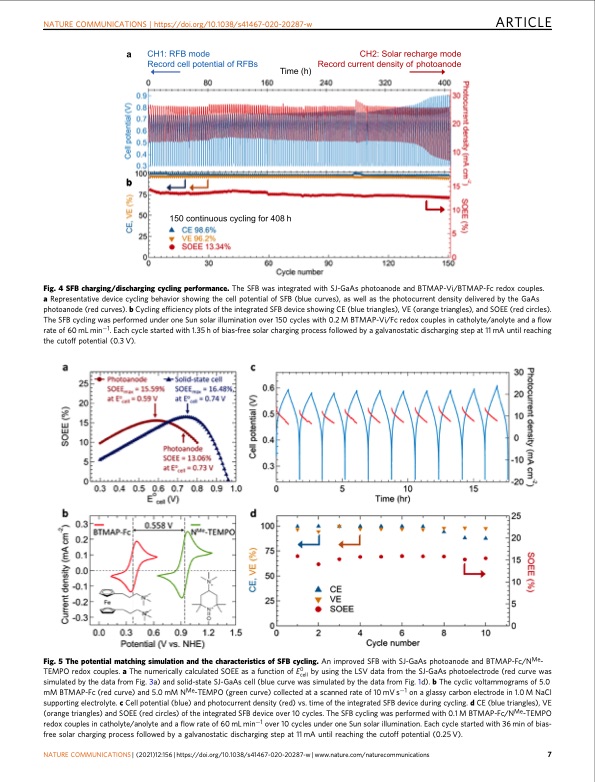
NATURE COMMUNICATIONS | https://doi.org/10.1038/s41467-020-20287-w ARTICLE Fig. 4 SFB charging/discharging cycling performance. The SFB was integrated with SJ-GaAs photoanode and BTMAP-Vi/BTMAP-Fc redox couples. a Representative device cycling behavior showing the cell potential of SFB (blue curves), as well as the photocurrent density delivered by the GaAs photoanode (red curves). b Cycling efficiency plots of the integrated SFB device showing CE (blue triangles), VE (orange triangles), and SOEE (red circles). The SFB cycling was performed under one Sun solar illumination over 150 cycles with 0.2 M BTMAP-Vi/Fc redox couples in catholyte/anolyte and a flow rate of 60 mL min−1. Each cycle started with 1.35 h of bias-free solar charging process followed by a galvanostatic discharging step at 11 mA until reaching the cutoff potential (0.3 V). Fig. 5 The potential matching simulation and the characteristics of SFB cycling. An improved SFB with SJ-GaAs photoanode and BTMAP-Fc/NMe- TEMPO redox couples. a The numerically calculated SOEE as a function of E0cell by using the LSV data from the SJ-GaAs photoelectrode (red curve was simulated by the data from Fig. 3a) and solid-state SJ-GaAs cell (blue curve was simulated by the data from Fig. 1d). b The cyclic voltammograms of 5.0 mM BTMAP-Fc (red curve) and 5.0 mM NMe-TEMPO (green curve) collected at a scanned rate of 10 mV s−1 on a glassy carbon electrode in 1.0 M NaCl supporting electrolyte. c Cell potential (blue) and photocurrent density (red) vs. time of the integrated SFB device during cycling. d CE (blue triangles), VE (orange triangles) and SOEE (red circles) of the integrated SFB device over 10 cycles. The SFB cycling was performed with 0.1 M BTMAP-Fc/NMe-TEMPO redox couples in catholyte/anolyte and a flow rate of 60 mL min−1 over 10 cycles under one Sun solar illumination. Each cycle started with 36 min of bias- free solar charging process followed by a galvanostatic discharging step at 11 mA until reaching the cutoff potential (0.25 V). NATURE COMMUNICATIONS | (2021)12:156 | https://doi.org/10.1038/s41467-020-20287-w | www.nature.com/naturecommunications 7PDF Image | flow battery enabled single-junction GaAs photoelectrode
PDF Search Title:
flow battery enabled single-junction GaAs photoelectrodeOriginal File Name Searched:
s41467-020-20287-w.pdfDIY PDF Search: Google It | Yahoo | Bing
Salgenx Redox Flow Battery Technology: Salt water flow battery technology with low cost and great energy density that can be used for power storage and thermal storage. Let us de-risk your production using our license. Our aqueous flow battery is less cost than Tesla Megapack and available faster. Redox flow battery. No membrane needed like with Vanadium, or Bromine. Salgenx flow battery
| CONTACT TEL: 608-238-6001 Email: greg@salgenx.com | RSS | AMP |