PDF Publication Title:
Text from PDF Page: 006
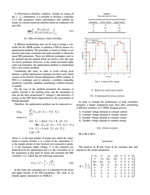
3) Performance+Stability condition: Finally, by means of the || · ||∞ formulation, it is possible to develop a controller C(s) that guarantees robust performance and stability by means of a mixed sensitivity problem based on conditions (19) and (20): TABLE I PARAMETERS BOUNDS D 0 1.0 Reference Output Wua (s)C (s)Sn (s) ∞ IV. PID OPTIMIZED THROUGH PSO C (s) Lower bound Upper bound I 0.1 1.0 Parameter P04 min We(s)Sn(s) . (21) A different methodology that can be used to design a con- troller for the VRFB system, is optimize a PID by means of a optimization problem. The procedure is based on define a cost function and some constraints that make possible to obtain the tuned PID parameters. There are different techniques such as the gradient descent method which are used to solve this type of convex problems. However, as the model presented imply some non-linearities, the optimization problem is transformed into a non-convex problem. Considering this issue, in order to avoid solving local minima, a global optimization technique has been used, which consist on the Particle Swarm Optimization (PSO) method. A PSO is a technique used to optimize a problem computing iteratively a possible candidate considering a defined measure of quality. For the case of the problem presented, the measure of quality selected is the tracking error, and the parameters to tune are the three proportional P , integral I and derivative D actions of the PID block implemented in the environment of Matlab-Simulink. Therefore, the optimization problem can be expressed as: 1.9 1.8 1.7 1.6 1.5 1.4 1.3 1.2 1.1 1 Voltage [V] minp subject to nk k=1 |Vref (k · Ts) − V (k · Ts)| 0.9 01234567 Time [s] 104 Fig. 6. Control of the voltage V. RESULTS AND DISCUSSION VI. COMPARATIVE EVALUATION In order to evaluate the performance of both controllers designed, a deeper comparison have been done considering 4 different scenarios of a VRFB charging process. 1) Constant voltage demand at constant current 2) Constant voltage demand at variable current 3) Variable voltage demand at constant current 4) Variable voltage demand at variable current x ̇ ( k · T s ) = A x ( k · T s ) + b · j ( k · T s ) +Bx · (Vref (k · Ts) − V (k · Ts)) · C(s) V (k · Ts) = h (x(k · Ts), j(k · Ts)) c(p) ≤ 0. BLA BLA BLA VII. CONCLUSIONS APPENDIX where nk is the total number of points into which the exper- iment is exactly divided, k is a point of the experiment, Ts is the sample period of time between two consecutive points, V is the measured output voltage, Vˆ is the estimated one obtained from the optimization and c is the constraints set of the parameters p that must be tuned and constitute the PID controller C(s) which has the following expression: (22) In this work, the constraints set c is conformed by the lower and upper bounds of the PID parameters. The value of its bounds appear summarized in TABLE I. The matrices A, B and vector b are constants that only depend on the model parameters: −k2 0 −k4 −2k5 0 0 00 0 −k3 2k4 3k5 0 0 0 0 3k2 2k3 −k4 0 0 A= 2·s 2k2 −k3 0 −k5 0 0 0 0 vc·d0 0 0 0 0000 0 0 0 0 0 0 0 0 I sD C(s)=P+ + 0 0 0 s 1+s 00000000 00000000PDF Image | H control of a redox flow battery overpotentials
PDF Search Title:
H control of a redox flow battery overpotentialsOriginal File Name Searched:
2523-Flow-controlling-tuning-for-the-voltage-flow-battery.pdfDIY PDF Search: Google It | Yahoo | Bing
Salgenx Redox Flow Battery Technology: Salt water flow battery technology with low cost and great energy density that can be used for power storage and thermal storage. Let us de-risk your production using our license. Our aqueous flow battery is less cost than Tesla Megapack and available faster. Redox flow battery. No membrane needed like with Vanadium, or Bromine. Salgenx flow battery
| CONTACT TEL: 608-238-6001 Email: greg@salgenx.com | RSS | AMP |