PDF Publication Title:
Text from PDF Page: 046
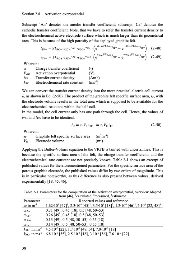
Section 2.8 Activation overpotential Subscript ‘An’ denotes the anodic transfer coefficient; subscript ‘Ca’ denotes the cathodic transfer coefficient. Note, that we have to refer the transfer current density to the electrochemical active electrode surface which is much larger than its geometrical area. This is because of the high porosity of the deployed graphite felt. iTF FkRC⋅c2CαAn ⋅c3CαCa ⋅ eαAnFEActGT eαCaFEActGT iTF FkRC⋅c4CαAn+⋅c5CαCa⋅eαAnFEActGT eαCaFEActGT Wherein: α Charge transfer coefficient (-) EAct Activation overpotential (V) iTF Transfer current density (Am-2) kRC Electrochemical rate constant (ms-1) (2-48) (2-49) We can convert the transfer current density into the more practical electric cell current IC as shown in Eq. (2-50). The product of the graphite felt specific surface area, sF, with the electrode volume results in the total area which is supposed to be available for the electrochemical reactions within the half-cell. In the model, the cell current only has one path through the cell. Hence, the values of iTF− and iTF+ have to be identical. IC sFVE iTF sFVE iTF (2-50) sF Graphite felt specific surface area (m2m-3) VE Electrode volume (m3) Applying the Butler-Volmer equation to the VRFB is tainted with uncertainties. This is because the specific surface area of the felt, the charge transfer coefficients and the electrochemical rate constant are not precisely known. Table 2-1 shows an excerpt of published values for the aforementioned parameters. For the specific surface area of the porous graphite electrode, the published values differ by two orders of magnitude. This is in particular noteworthy, as this difference is also present between values, derived experimentally [18, 45, 46]. Table 2-1. Parameters for the computation of the activation overpotential, overview adapted from [46], 1calculated, 2measured, 3estimated Wherein: Parameter sF in m-1 α An− α Ca− α An+ α Ca+ kRC− in ms-1 kRC+ in ms-1 Reported values and reference 1.62·104 [47]1, 2.3·104 [45]2, 3.5·104 [18]2, 1.2·106 [46]2, 2·106 [22, 48]3 0.31 [49], 0.45 [18], 0.5 [48, 50–53] 0.26 [49], 0.45 [18], 0.5 [48, 50–53] 0.13 [49], 0.5 [48, 50–53], 0.55 [18] 0.14 [49], 0.5 [48, 50–53], 0.55 [18] 4.5·10-6 [22], 1.7·10-7 [48, 54], 7.0·10-8 [18] 6.8·10-7 [55], 2.5·10-8 [18], 3·10-9 [56], 7.6·10-9 [22] 38PDF Image | Model-based Design Vanadium Redox Flow Batteries
PDF Search Title:
Model-based Design Vanadium Redox Flow BatteriesOriginal File Name Searched:
10-5445IR1000070670.pdfDIY PDF Search: Google It | Yahoo | Bing
Salgenx Redox Flow Battery Technology: Salt water flow battery technology with low cost and great energy density that can be used for power storage and thermal storage. Let us de-risk your production using our license. Our aqueous flow battery is less cost than Tesla Megapack and available faster. Redox flow battery. No membrane needed like with Vanadium, or Bromine. Salgenx flow battery
| CONTACT TEL: 608-238-6001 Email: greg@salgenx.com | RSS | AMP |