PDF Publication Title:
Text from PDF Page: 106
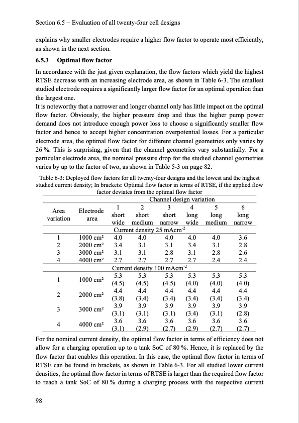
Section 6.5 Evaluation of all twenty-four cell designs explains why smaller electrodes require a higher flow factor to operate most efficiently, as shown in the next section. 6.5.3 Optimal flow factor In accordance with the just given explanation, the flow factors which yield the highest RTSE decrease with an increasing electrode area, as shown in Table 6-3. The smallest studied electrode requires a significantly larger flow factor for an optimal operation than the largest one. It is noteworthy that a narrower and longer channel only has little impact on the optimal flow factor. Obviously, the higher pressure drop and thus the higher pump power demand does not introduce enough power loss to choose a significantly smaller flow factor and hence to accept higher concentration overpotential losses. For a particular electrode area, the optimal flow factor for different channel geometries only varies by 26 %. This is surprising, given that the channel geometries vary substantially. For a particular electrode area, the nominal pressure drop for the studied channel geometries varies by up to the factor of two, as shown in Table 5-3 on page 82. Table 6-3: Deployed flow factors for all twenty-four designs and the lowest and the highest studied current density; In brackets: Optimal flow factor in terms of RTSE, if the applied flow factor deviates from the optimal flow factor Area variation 1 2 3 4 1 2 3 4 Electrode area 1000 cm2 2000 cm2 3000 cm2 4000 cm2 1000 cm2 2000 cm2 3000 cm2 4000 cm2 Channel design variation 123456 short short short long long long wide medium narrow wide medium narrow Current density 25 mAcm-2 4.0 4.0 4.0 4.0 4.0 3.6 3.4 3.1 3.1 3.4 3.1 2.8 3.1 3.1 2.8 3.1 2.8 2.6 2.7 2.7 2.7 2.7 2.4 2.4 Current density 100 mAcm-2 5.3 5.3 5.3 5.3 5.3 5.3 (4.5) (4.5) (4.5) (4.0) (4.0) (4.0) 4.4 4.4 4.4 4.4 4.4 4.4 (3.8) (3.4) (3.4) (3.4) (3.4) (3.4) 3.9 3.9 3.9 3.9 3.9 3.9 (3.1) (3.1) (3.1) (3.4) (3.1) (2.8) 3.6 3.6 3.6 3.6 3.6 3.6 (3.1) (2.9) (2.7) (2.9) (2.7) (2.7) For the nominal allow for a charging operation up to a tank SoC of 80 %. Hence, it is replaced by the flow factor that enables this operation. In this case, the optimal flow factor in terms of RTSE can be found in brackets, as shown in Table 6-3. For all studied lower current densities, the optimal flow factor in terms of RTSE is larger than the required flow factor to reach a tank SoC of 80 % during a charging process with the respective current 98 current density, the optimal flow factor in terms of efficiency does notPDF Image | Model-based Design Vanadium Redox Flow Batteries
PDF Search Title:
Model-based Design Vanadium Redox Flow BatteriesOriginal File Name Searched:
10-5445IR1000070670.pdfDIY PDF Search: Google It | Yahoo | Bing
Salgenx Redox Flow Battery Technology: Salt water flow battery technology with low cost and great energy density that can be used for power storage and thermal storage. Let us de-risk your production using our license. Our aqueous flow battery is less cost than Tesla Megapack and available faster. Redox flow battery. No membrane needed like with Vanadium, or Bromine. Salgenx flow battery
| CONTACT TEL: 608-238-6001 Email: greg@salgenx.com | RSS | AMP |