PDF Publication Title:
Text from PDF Page: 136
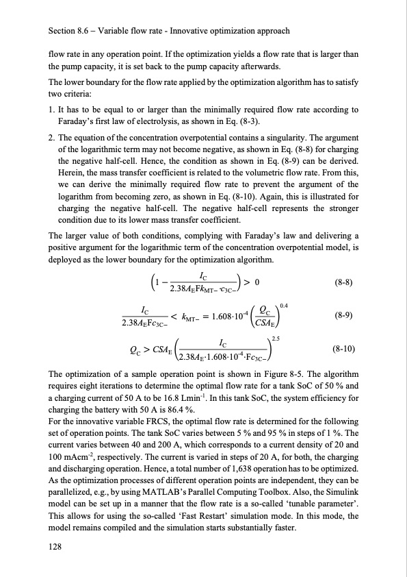
Section 8.6 Variable flow rate - Innovative optimization approach flow rate in any operation point. If the optimization yields a flow rate that is larger than the pump capacity, it is set back to the pump capacity afterwards. The lower boundary for the flow rate applied by the optimization algorithm has to satisfy two criteria: 1. It has to be equal to or larger than the minimally required flow rate according to Faraday’s first law of electrolysis, as shown in Eq. (8-3). 2. The equation of the concentration overpotential contains a singularity. The argument of the logarithmic term may not become negative, as shown in Eq. (8-8) for charging the negative half-cell. Hence, the condition as shown in Eq. (8-9) can be derived. Herein, the mass transfer coefficient is related to the volumetric flow rate. From this, we can derive the minimally required flow rate to prevent the argument of the logarithm from becoming zero, as shown in Eq. (8-10). Again, this is illustrated for charging the negative half-cell. The negative half-cell represents the stronger condition due to its lower mass transfer coefficient. The larger value of both conditions, complying with Faraday’s law and delivering a positive argument for the logarithmic term of the concentration overpotential model, is deployed as the lower boundary for the optimization algorithm. 1 IC IC 0 (8-8) 2.38AE FkMT ⋅c3C kMT 1.608⋅10-4 Q 0.4 C CSAE 2.5 (8-9) (8-10) 2.38AE Fc3C Q CSAE C I C 2.38AE ⋅1.608⋅10-4 ⋅Fc3C The optimization of a sample operation point is shown in Figure 8-5. The algorithm requires eight iterations to determine the optimal flow rate for a tank SoC of 50 % and a charging current of 50 A to be 16.8 Lmin-1. In this tank SoC, the system efficiency for charging the battery with 50 A is 86.4 %. For the innovative variable FRCS, the optimal flow rate is determined for the following set of operation points. The tank SoC varies between 5 % and 95 % in steps of 1 %. The current varies between 40 and 200 A, which corresponds to a current density of 20 and 100 mAcm-2, respectively. The current is varied in steps of 20 A, for both, the charging and discharging operation. Hence, a total number of 1,638 operation has to be optimized. As the optimization processes of different operation points are independent, they can be parallelized, e.g., by using MATLAB’s Parallel Computing Toolbox. Also, the Simulink model can be set up in a manner that the flow rate is a so-called ‘tunable parameter’. This allows for using the so-called ‘Fast Restart’ simulation mode. In this mode, the model remains compiled and the simulation starts substantially faster. 128PDF Image | Model-based Design Vanadium Redox Flow Batteries

PDF Search Title:
Model-based Design Vanadium Redox Flow BatteriesOriginal File Name Searched:
10-5445IR1000070670.pdfDIY PDF Search: Google It | Yahoo | Bing
Salgenx Redox Flow Battery Technology: Salt water flow battery technology with low cost and great energy density that can be used for power storage and thermal storage. Let us de-risk your production using our license. Our aqueous flow battery is less cost than Tesla Megapack and available faster. Redox flow battery. No membrane needed like with Vanadium, or Bromine. Salgenx flow battery
| CONTACT TEL: 608-238-6001 Email: greg@salgenx.com | RSS | AMP |