PDF Publication Title:
Text from PDF Page: 056
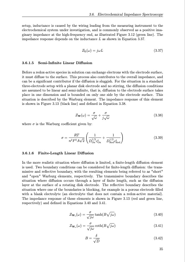
where σ is the Warburg coefficient given by: RT1 1 3.6. Electrochemical Impedance Spectroscopy setup, inductance is caused by the wiring leading from the measuring instrument to the electrochemical system under investigation, and is commonly observed as a positive ima- ginary impedance at the high-frequency end, as illustrated Figure 3.12 (green line). The impedance response depends on the inductance L as shown in Equation 3.37. ZL(ω) = jωL (3.37) 3.6.1.5 Semi-Infinite Linear Diffusion Before a redox-active species in solution can exchange electrons with the electrode surface, it must diffuse to the surface. This process also contributes to the overall impedance, and can be a significant contributor if the diffusion is sluggish. For the situation in a standard three-electrode setup with a planar disk electrode and no stirring, the diffusion conditions are assumed to be linear and semi-infinite, that is, diffusion to the electrode surface takes place in one dimension and is bounded on only one side by the electrode surface. This situation is described by the Warburg element. The impedance response of this element is shown in Figure 3.13 (black line) and defined in Equation 3.38. σσ ZW(ω) = √ω + j√ω (3.38) (3.39) σ = n2F 2A√2 D1/2c∗ + D1/2 c∗ Ox Ox Red Red 3.6.1.6 Finite-Length Linear Diffusion In the more realistic situation where diffusion is limited, a finite-length diffusion element is used. Two boundary conditions can be considered for finite-length diffusion: the trans- missive and reflective boundary, with the resulting elements being referred to as "short" and "open" Warburg elements, respectively. The transmissive boundary describes the situation where diffusion occurs through a layer of finite length, such as the diffusion layer at the surface of a rotating disk electrode. The reflective boundary describes the situation where one of the boundaries is blocking, for example in a porous electrode filled with a blank electrolyte (an electrolyte that does not contain a redox-active material). The impedance response of these elements is shown in Figure 3.13 (red and green line, respectively) and defined in Equations 3.40 and 3.41. Z (ω) = √σ jω Z (ω) = √σ jω tanh(Bjω) coth(Bjω) (3.40) (3.41) (3.42) 35 Ws Wo B = √δ DPDF Image | Organic Redox Flow Batteries 2023

PDF Search Title:
Organic Redox Flow Batteries 2023Original File Name Searched:
PhD_thesis_final_dorhoff_4_.pdfDIY PDF Search: Google It | Yahoo | Bing
Salgenx Redox Flow Battery Technology: Salt water flow battery technology with low cost and great energy density that can be used for power storage and thermal storage. Let us de-risk your production using our license. Our aqueous flow battery is less cost than Tesla Megapack and available faster. Redox flow battery. No membrane needed like with Vanadium, or Bromine. Salgenx flow battery
| CONTACT TEL: 608-238-6001 Email: greg@salgenx.com | RSS | AMP |