PDF Publication Title:
Text from PDF Page: 059
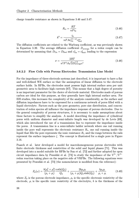
Chapter 3. Characterisation Methods charge transfer resistance as shown in Equations 3.46 and 3.47: Rct = RT nF i0 k0 = i0 nF Ac∗(1−α) c∗α Ox Red (3.46) (3.47) The diffusion coefficients are related to the Warburg coefficient, as was previously shown in Equation 3.39. The average diffusion coefficient Daverage for a redox couple can be determined by assuming that DOx = DRed and c∗Ox = c∗Red, leading to the expression 2RT σ = n2F2A√2D1/2 c∗ (3.48) average 3.6.2.2 Flow Cells with Porous Electrodes: Transmission Line Model For the impedance of three-electrode systems just described, it is important to have a flat and well-defined WE surface so that the assumption of linear diffusion to the electrode surface holds. In RFBs, the electrodes must possess high internal surface area per unit geometric area to facilitate high currents [67]. This means that a high degree of porosity is an important parameter for the choice of electrode material. Electrodes made of porous carbon are ideal for this purpose, as they generally have high internal surface area. For EIS studies, this increases the complexity of the analysis considerably, as the surface and diffusion impedances have to be expressed for a continuous network of pores filled with a liquid electrolyte. Factors such as the pore geometry, pore size distribution, and concen- tration of redox species all influence the impedance response of porous electrodes. Due to the general complexity of porous structures, it is necessary to make assumptions about these factors to simplify the analysis. A model describing the impedance of cylindrical pores with uniform diameter and semi-infinite length was developed by de Levie [69], which also introduced the use of a transmission line to represent the impedance inside the pores. A transmission line is a semi-infinite ladder network where one rail running inside the pore wall represents the electronic resistance Re, one rail running inside the liquid that fills the pore represents the ionic resistance Ri, and the rungs between the rails represent the surface impedance ζ. The concept is illustrated for a single pore in Figure 3.16. Paasch et al. later developed a model for macrohomogeneous porous electrodes with finite electrode thickness and resistivities of the solid and liquid phases [71]. This was developed into a model suitable for RFBs by Sun et al. [72] and further adopted for open circuit impedance data by Pezeshki et al. [73] to study the impedance of the V2+/V3+ redox reaction taking place on the negative side of VRFBs. The following equations were presented by Pezeshki et al. [73] (the nomenclature is modified from the reference): Zp(ω) = b(ρ2e + ρ2i ) coth(Q2) + 2bρeρi + bρeρi (3.49) (ρe + ρi) Q2 (ρe + ρi)Q2 sinh(Q2) ρe + ρi where Zp is the porous electrode impedance, ρe is the specific electronic resistivity of the electrode, ρi is the specific ionic resistivity of the electrolyte, b is the thickness of the 38PDF Image | Organic Redox Flow Batteries 2023

PDF Search Title:
Organic Redox Flow Batteries 2023Original File Name Searched:
PhD_thesis_final_dorhoff_4_.pdfDIY PDF Search: Google It | Yahoo | Bing
Salgenx Redox Flow Battery Technology: Salt water flow battery technology with low cost and great energy density that can be used for power storage and thermal storage. Let us de-risk your production using our license. Our aqueous flow battery is less cost than Tesla Megapack and available faster. Redox flow battery. No membrane needed like with Vanadium, or Bromine. Salgenx flow battery
| CONTACT TEL: 608-238-6001 Email: greg@salgenx.com | RSS | AMP |