PDF Publication Title:
Text from PDF Page: 013
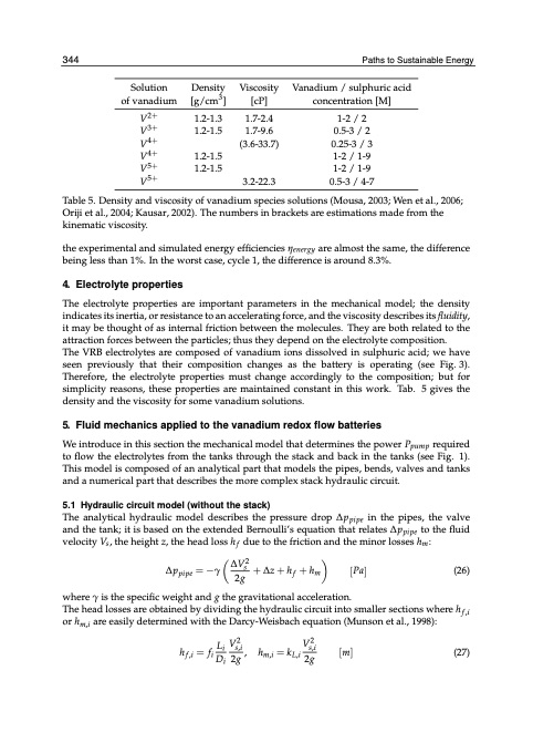
31244 Solution Density of vanadium [g/cm3] V2+ 1.2-1.3 V3+ 1.2-1.5 V4+ V4+ 1.2-1.5 V5+ 1.2-1.5 V5+ Viscosity [cP] 1.7-2.4 1.7-9.6 (3.6-33.7) 3.2-22.3 Paths tSouSsutastianianbalbeleEEnneergrgyy Vanadium / sulphuric acid concentration [M] 1-2 / 2 0.5-3 / 2 0.25-3 / 3 1-2 / 1-9 1-2 / 1-9 0.5-3 / 4-7 Table 5. Density and viscosity of vanadium species solutions (Mousa, 2003; Wen et al., 2006; Oriji et al., 2004; Kausar, 2002). The numbers in brackets are estimations made from the kinematic viscosity. the experimental and simulated energy efficiencies ηenergy are almost the same, the difference being less than 1%. In the worst case, cycle 1, the difference is around 8.3%. 4. Electrolyte properties The electrolyte properties are important parameters in the mechanical model; the density indicates its inertia, or resistance to an accelerating force, and the viscosity describes its fluidity, it may be thought of as internal friction between the molecules. They are both related to the attraction forces between the particles; thus they depend on the electrolyte composition. The VRB electrolytes are composed of vanadium ions dissolved in sulphuric acid; we have seen previously that their composition changes as the battery is operating (see Fig. 3). Therefore, the electrolyte properties must change accordingly to the composition; but for simplicity reasons, these properties are maintained constant in this work. Tab. 5 gives the density and the viscosity for some vanadium solutions. 5. Fluid mechanics applied to the vanadium redox flow batteries We introduce in this section the mechanical model that determines the power Ppump required to flow the electrolytes from the tanks through the stack and back in the tanks (see Fig. 1). This model is composed of an analytical part that models the pipes, bends, valves and tanks and a numerical part that describes the more complex stack hydraulic circuit. 5.1 Hydraulic circuit model (without the stack) The analytical hydraulic model describes the pressure drop Δppipe in the pipes, the valve and the tank; it is based on the extended Bernoulli’s equation that relates Δppipe to the fluid velocity Vs, the height z, the head loss hf due to the friction and the minor losses hm: ΔVs2 Δppipe =−γ 2g +Δz+hf +hm [Pa] (26) where γ is the specific weight and g the gravitational acceleration. The head losses are obtained by dividing the hydraulic circuit into smaller sections where h f ,i or hm,i are easily determined with the Darcy-Weisbach equation (Munson et al., 1998): L V2 V2 hf,i=fi i s,i, hm,i=kL,i s,i [m] (27) Di 2g 2gPDF Image | Understanding the Vanadium Redox Flow Batteries
PDF Search Title:
Understanding the Vanadium Redox Flow BatteriesOriginal File Name Searched:
12523.pdfDIY PDF Search: Google It | Yahoo | Bing
Salgenx Redox Flow Battery Technology: Salt water flow battery technology with low cost and great energy density that can be used for power storage and thermal storage. Let us de-risk your production using our license. Our aqueous flow battery is less cost than Tesla Megapack and available faster. Redox flow battery. No membrane needed like with Vanadium, or Bromine. Salgenx flow battery
| CONTACT TEL: 608-238-6001 Email: greg@salgenx.com | RSS | AMP |