PDF Publication Title:
Text from PDF Page: 002
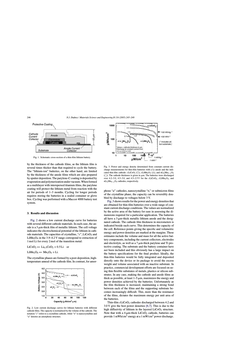
246 N.J. Dudney / Materials Science and Engineering B 116 (2005) 245–249 Fig. 1. Schematic cross-section of a thin-film lithium battery. by the thickness of the cathode films, as the lithium film is several times thicker than that required to cycle the battery. The “lithium-ion” batteries, on the other hand, are limited by the thickness of the anode films which are also prepared by sputter deposition. The parylene-C coating is deposited by evaporation and polymerization under vacuum. When formed as a multilayer with interspersed titanium films, the parylene coating will protect the lithium metal from reaction with the air for periods of 1–3 months. Cycling for longer periods requires storing the batteries in a sealed container or glove box. Cycling was performed with a Maccor 4000 battery test system. 3. Results and discussion Fig. 2 shows a low current discharge curve for batteries with several different cathode materials. In each case, the an- ode is a 3 m-thick film of metallic lithium. The cell voltage indicates the electrochemical potential of the lithium in cath- ode materials. The capacities of crystalline, “c”, LiCoO2 and LiMn2O4 in the 3.9–4.2 V range correspond to extraction of 1 mol Li for every 2 mol of the transition metal: LiCoO2 ↔ Li0.5CoO2 + 0.5 Li or LiMn2O4 ↔ Mn2O4 + Li. The crystalline phases are formed by a post-deposition, high- temperature anneal of the cathode film. In contrast, for amor- Fig. 2. Low current discharge curves for lithium batteries with different cathode films. The capacity is normalized by the volume of the cathode. The notation “c” refers to a crystalline cathode, while “n” is nanocrystalline and “a” denotes an amorphous structure. Fig. 3. Power and energy density determined from constant current dis- charge measurements for thin-film batteries with a Li anode and the indi- cated thin-film cathode: cLiCoO2 (), cLiMn2O4 (△), and nLixMn2−yO4 (⃝). The cathode thickness is given in m. The batteries were discharged over 4.2–3.0, 4.5–3.0, and 4.5–2.5 V for the cLiCoO2 , cLiMn2 O4 , and nLixMn2−yO4 cathodes, respectively. phous “a” cathodes, nanocrystalline “n,” or submicron films of the crystalline phase, the capacity can be reversibly dou- bled by discharge to voltages below 3 V. Fig. 3 shows results for the power and energy densities that are obtained for thin-film batteries over a wide range of con- stant current discharge conditions. The values are normalized by the active area of the battery for ease in assessing the di- mensions required for a particular application. The batteries all have a 3 m-thick metallic lithium anode and the desig- nated cathode. The cathode film thickness in micrometers is indicated beside each curve. This determines the capacity of the cell. Reference points giving the specific and volumetric energy and power densities are marked at the margins. These estimates include the volume and mass for all the active bat- tery components, including the current collectors, electrodes and electrolyte, as well as a 7 m-thick parylene and Ti pro- tective coating. The substrate and the battery container have not been included and this obviously has a large impact on the battery specifications for the final product. Ideally, the thin-film batteries would be fully integrated and deposited directly onto the device or its package to avoid the excess weight and volume associated with an inactive substrate. In practice, commercial development efforts are focused on us- ing thin flexible substrates of metals, plastics or silicon sub- strates. In any case, making the cathode and anode films as thick as possible, at least 1–5 m, maximizes the energy and power densities achieved by the batteries. Unfortunately as the film thickness is increased, maintaining a strong bond between each of the films and the supporting substrate be- comes increasingly difficult. This, more than the resistance of the films, dictates the maximum energy per unit area of the batteries. Thin-film cLiCoO2 cathodes discharged between 4.2 and 3.0 V give the best power densities [6,7]. This is due to the high diffusivity of lithium in the layered LiCoO2 structure. Note that with a 4 m-thick LiCoO2 cathode, batteries can provide 1 mWh/cm2 energy at a 1 mW/cm2 power discharge.PDF Image | Solid-state thin-film rechargeable batteries
PDF Search Title:
Solid-state thin-film rechargeable batteriesOriginal File Name Searched:
120311.pdfDIY PDF Search: Google It | Yahoo | Bing
Sulfur Deposition on Carbon Nanofibers using Supercritical CO2 Sulfur Deposition on Carbon Nanofibers using Supercritical CO2. Gamma sulfur also known as mother of pearl sulfur and nacreous sulfur... More Info
CO2 Organic Rankine Cycle Experimenter Platform The supercritical CO2 phase change system is both a heat pump and organic rankine cycle which can be used for those purposes and as a supercritical extractor for advanced subcritical and supercritical extraction technology. Uses include producing nanoparticles, precious metal CO2 extraction, lithium battery recycling, and other applications... More Info
| CONTACT TEL: 608-238-6001 Email: greg@infinityturbine.com | RSS | AMP |