PDF Publication Title:
Text from PDF Page: 013
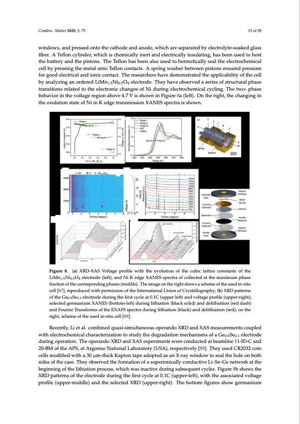
Condens. Matter 2020, 5, 75 13 of 28 windows, and pressed onto the cathode and anode, which are separated by electrolyte-soaked glass fiber. A Teflon cylinder, which is chemically inert and electrically insulating, has been used to host the battery and the pistons. The Teflon has been also used to hermetically seal the electrochemical cell by pressing the metal onto Teflon contacts. A spring washer between pistons ensured pressure for good electrical and ionic contact. The researchers have demonstrated the applicability of the cell by analyzing an ordered LiMn1.5Ni0.5O4 electrode. They have observed a series of structural phase transitions related to the electronic changes of Ni during electrochemical cycling. The two- phase behavior in the voltage region above 4.7 V is shown in Figure 8a (left). On the right, the changing in theoCxoindeantsi.oMnatstetra2t0e20o,5f,NxiinKedgetransmissionXANESspectraisshown. 14of30 Figure 8. (a) XRD-XAS Voltage profile with the evolution of the cubic lattice constants of the Figure 8. (a) XRD-XAS Voltage profile with the evolution of the cubic lattice constants of the LiMnLiMNn1i.5NiO0.5Oe4lelcetcrtoroddee((lleft), andNiiKeeddggeeXXAANNESESspsepctercatroaf ocofllceocltleedctaetdthaetmthaeximauxmimpuhmasephase 1.5 0.5 4 fractiforanctoiofnthoefcthoerrceosrpreosnpdoindginpghpashease(ms (imdidldel)e.)T. Thheeimimaageontherightshowssaasscchheemmeeofotfhteheusuesdeidni-n-situ situ cell [87], reproduced with permission of the International Union of Crystallography; (b) XRD cell [87], reproduced with permission of the International Union of Crystallography; (b) XRD patterns patterns of the Ge0.9Se0.1 electrode during the first cycle at 0.1C (upper left) and voltage profile (upper- of the Ge0.9Se0.1 electrode during the first cycle at 0.1C (upper left) and voltage profile (upper-right); right); selected germanium XANES (bottom-left) during lithiation (black solid) and delithiation (red selected germanium XANES (bottom-left) during lithiation (black solid) and delithiation (red dash) dash) and Fourier Transforms of the EXAFS spectra during lithiation (black) and delithiation (red); and Fourier Transforms of the EXAFS spectra during lithiation (black) and delithiation (red); on the on the right, scheme of the used in-situ cell [89]. right, scheme of the used in-situ cell [89]. Raman spectroscopy is another technique often coupled to XRD for battery studies. It is used to Recently, Li et al. combined quasi-simultaneous operando XRD and XAS measurements coupled explore the variation in the local structure and oxidation state, as well as the thermal stability of with electrochemical characterization to study the degradation mechanisms of a Ge0.9Se0.1 electrode electrode surfaces or electrode-electrolyte interfaces during charge-discharge and heat treatment. during operation. The operando XRD and XAS experiments were conducted at beamline 11-ID-C and Tardif and co-authors combined operando Raman spectroscopy and synchrotron XRD to probe the 20-BMevoluftihoenAofPsSt,reastsAanrgdotnhneelNasatitciosntralinLainboLrIaBtoanryod(eUsSmAa)d,ereosfpcercytsitvaelliyne[8s9il]i.coTnhneyanuospeadrtiCclRes20(S3i2coin cellsNmPosd) [i9fi0e]d. Twheiythuase3d0aμnmin-tshitiuckceKllacopmtopnostaedpeofatdwoopstteadinalesssansteXe-lrealeycwtroindedsoawndtoa pseoalylettherhkoelteonoen both body with a μ M-thick window for high chemical stability and low background contribution. On the sides of the case. They observed the formation of a superionically conductive Li–Se–Ge network at the CRG beamline BM32 at the European Synchrotron (ESRF, Grenoble, France), they observed the core– beginning of the lithiation process, which was inactive during subsequent cycles. Figure 8b shows the shell Si NP structure by analysing the intensity and position variations of the XRD and Raman peaks, XRD patterns of the electrode during the first cycle at 0.1C (upper-left), with the associated voltage showing how the pressure exerted from the amorphized shell onto the continuously shrinking profile (upper-middle) and the selected XRD (upper-right). The bottom figures show germanium crystalline core is responsible for electrochemically driven variations of the internal stress. Figure 9 shows the time dependence of the cell potential and the transferred specific capacity during the first two cycles (first graph), the integrated X-ray diffraction intensity (second graph), and the strain, ε, relative to the initial state (third graph). The successive steps of the lithiation/delithiation related to distinct mechanisms are schematically shown in the bottom graph. On the right, a sketch of the custom battery half-cell and the experimental XRD setup are shown.PDF Image | Synchrotron-Based X-ray Diffraction for Lithium-Ion Batteries
PDF Search Title:
Synchrotron-Based X-ray Diffraction for Lithium-Ion BatteriesOriginal File Name Searched:
condensedmatter-05-00075.pdfDIY PDF Search: Google It | Yahoo | Bing
Sulfur Deposition on Carbon Nanofibers using Supercritical CO2 Sulfur Deposition on Carbon Nanofibers using Supercritical CO2. Gamma sulfur also known as mother of pearl sulfur and nacreous sulfur... More Info
CO2 Organic Rankine Cycle Experimenter Platform The supercritical CO2 phase change system is both a heat pump and organic rankine cycle which can be used for those purposes and as a supercritical extractor for advanced subcritical and supercritical extraction technology. Uses include producing nanoparticles, precious metal CO2 extraction, lithium battery recycling, and other applications... More Info
| CONTACT TEL: 608-238-6001 Email: greg@infinityturbine.com | RSS | AMP |