PDF Publication Title:
Text from PDF Page: 004
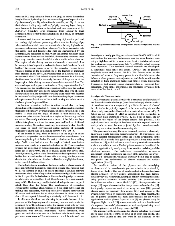
518 PATEL ET AL. bursts and CL drops abruptly from B to C; Fig. 1b shows the laminar long bubble at S1 develops into an extended region of separation for CLs between C1 and D1, where flow is unstable; and Fig. 1c shows the turbulent trailing edge stall. A2 B2 C2 D2 boundary layer changes from laminar to transition to turbulent and then separates at C2. A3B3C3D3 boundary layer progresses from laminar to local separation, then to turbulent reattachment, and finally to turbulent separation. Laminar stall is caused as a result of a very high suction peak and succeeding high adverse pressure gradient near the leading edge, whereas turbulent stall occurs as a result of a relatively high adverse pressure gradient near the aft part of airfoil. The flows associated with thin-airfoil stall and leading-edge stall are characterized by the accompanying separation bubble. When the laminar boundary layer separates from the surface of the airfoil, the resulting separated shear layer may curve back onto the airfoil surface within a short distance. The region of circulatory motion underneath a separated flow between points of separation and reattachment is defined as a “short bubble.” In certain cases, however, the separated viscous layer, which is formed in the neighborhood of the location of minimum peak pressure on the airfoil, may not reattach to the surface at all or may reattach after 0.2–0.3 chord lengths downstream. In either case, the flow over the airfoil is unsteady because of the presence of the large region of circulatory motion underneath the separated flow. The extended separated region is defined as a “long separation bubble.” The presence of the short laminar separation bubble near the leading edge of the airfoil may give rise to laminar stall. This type of stall is distinguished from the turbulent or trailing-edge stall by the fact that in the case of trailing-edge stall, turbulent boundary-layer separation takes place near the aft end of the airfoil causing the existence of a sizable region of separated flow. A laminar separation bubble is either called short or long depending on the magnitude of Re (based on velocity and momentum thickness of boundary-layer separation) and pressure gradient. If the bubble is short and the angle of attack is then increased, the separation point moves forward to a region of increasing surface curvature. Eventually turbulent reattachment of the full shear layer fails to take place, and there is a consequent sudden loss of lift and increase in drag. Separation involving formation of a short bubble can occur on most conventional airfoil sections of moderate thickness to chord ratio in the range of 0:09 < t=c < 0:15. If the bubble is long, then an increase in the angle of attack produces a progressive rearward movement of the reattachment, thus increasing the length of the bubble until it coincides with the trailing edge. Stall is reached at about this angle of attack; any further increase in results in a gradual reduction in lift. This separation process can also occur on most conventional thin airfoils having t=c ratios up to about 0.09, and it is usually called thin-airfoil stall. Aerodynamically, whereas the formation and development of a long bubble has a considerable adverse effect on drag via the pressure distribution, the existence of a short bubble has a negligible effect up to the harmful stall condition. The turbulent separation from the trailing edge is characteristic of most conventional thick airfoil sections in a range of t=c greater than 0.12. An increase in angle of attack produces a gradual forward movement of the point of separation and steady and gradual decrease in lift. It is possible for both short bubble and trailing-edge separation to exist on the same families of airfoils at the same time over a certain range of Re . The former generally starts to develop at a lower angle of attack than does the latter. This combination of separation consequently displays characteristics of both short bubble and the trailing-edge separation, with the possibility of either a semirounded lift curve peak followed by an abrupt decrease in lift or a relative sharp lift curve peak followed by a relatively rapid decrease in lift. In all cases, the flow over the wing is unsteady because of the presence of the large region of circulatory motion underneath the separated flow. The ultimate goal of the present work is to develop methods to identify incipient flow separation by correlating pressure fluctuations with physical phenomena (bubble formation, wind gusts, etc.) which can be used as a feedback rule for switching the plasma actuator on or off for autonomous control. In this work, we Exposed electrode Induced flow Covered electrode Substrate a.c voltage Dielectric Fig. 2 actuator. investigate a slowly pitching two-dimensional NACA 0015 airfoil and capture the pressure fluctuations near the wing leading edge using a high-bandwidth pressure sensor located just downstream of the leading-edge plasma actuator (at x=c 0:05) to detect incipient flow separation. Two feedback control methods are developed: 1) amplitude peak sense and control (APSC), and 2) pressure amplitude sense and control (PASC). The former relies on the detection of actuator frequency peaks in the flowfield under the influence of an upstream unsteady actuator, and the latter relies on the detection of high amplitude peaks over ranges of key preselected frequencies that exhibit strong characteristics of incipient flow separation. Wind tunnel experiments are conducted to validate both methods of feedback control. Aerodynamic Plasma Actuator An aerodynamic plasma actuator is a particular configuration of the dielectric-barrier discharge (a surface discharge) which consists of two electrodes that are separated by a dielectric material. One of the electrodes is typically exposed to the surrounding air and the other is fully encapsulated by a dielectric material, as shown in Fig. 2. When an a.c. voltage (5 kHz) is supplied to the electrodes, at sufficiently high amplitude levels (3–12 kV peak to peak), the air ionizes in the region of the largest electric field potential. This typically occurs at the edge of the electrode that is exposed to the air and spreads out over the area projected by the covered electrode, directing momentum into the surrounding air. The process of ionizing the air in this configuration is classically known as a single-dielectric-barrier discharge [12]. The basis of this plasma actuator configuration is that the ionized air (plasma) in the presence of an electric field gradient produces a body force on the ambient air [13], which induces a virtual aerodynamic shape over the surface around the actuator. The body-force vector can be tailored for a given application by configuring the orientation and design of the electrode geometry. The body-force representation is also a convenient form to incorporate the effect of the actuators in Navier– Stokes (NS) simulations, which are currently being used to design and predict the performance of plasma actuators for various applications [14–16]. An excellent review of the physics and the underlying mechanisms of the aerodynamic plasma actuator is provided by Enloe et al. [12,13]. The use of single-dielectric-barrier-discharge plasma actuators for flow-control applications has been demon- strated by several researchers. Examples of flow-control applications using plasma actuators include exciting 3-D boundary-layer instabilities on a sharp cone at Mach 3.5 [17], lift augmentation on wings [18], separation control for low-pressure turbine blades [19], leading-edge separation control on wing sections [20], phased plasma arrays for unsteady flow control [21], and control of the dynamic stall vortex on oscillating airfoils [22]. More recently, the use of plasma actuators has been demonstrated for air vehicle applications such as plasma flaps and slats [2] and plasma wing for hingeless flight control [23]. A new method to enhance the effects of a low-power “unsteady” plasma actuator are investigated using novel plasma-optimized airfoil design concepts [24]. The majority of the applications for plasma actuators referenced above deals with the control of flows in an open-loop mode. The authors were unable to find any work in the literature on the Asymmetric electrode arrangement of an aerodynamic plasmaPDF Image | Autonomous Sensing and Control of Wing Stall Using a Smart Plasma Slat
PDF Search Title:
Autonomous Sensing and Control of Wing Stall Using a Smart Plasma SlatOriginal File Name Searched:
Autonomous_Sensing_and_Control_of_Wing_Stall_Using.pdfDIY PDF Search: Google It | Yahoo | Bing
NFT (Non Fungible Token): Buy our tech, design, development or system NFT and become part of our tech NFT network... More Info
IT XR Project Redstone NFT Available for Sale: NFT for high tech turbine design with one part 3D printed counter-rotating energy turbine. Be part of the future with this NFT. Can be bought and sold but only one design NFT exists. Royalties go to the developer (Infinity) to keep enhancing design and applications... More Info
Infinity Turbine IT XR Project Redstone Design: NFT for sale... NFT for high tech turbine design with one part 3D printed counter-rotating energy turbine. Includes all rights to this turbine design, including license for Fluid Handling Block I and II for the turbine assembly and housing. The NFT includes the blueprints (cad/cam), revenue streams, and all future development of the IT XR Project Redstone... More Info
Infinity Turbine ROT Radial Outflow Turbine 24 Design and Worldwide Rights: NFT for sale... NFT for the ROT 24 energy turbine. Be part of the future with this NFT. This design can be bought and sold but only one design NFT exists. You may manufacture the unit, or get the revenues from its sale from Infinity Turbine. Royalties go to the developer (Infinity) to keep enhancing design and applications... More Info
Infinity Supercritical CO2 10 Liter Extractor Design and Worldwide Rights: The Infinity Supercritical 10L CO2 extractor is for botanical oil extraction, which is rich in terpenes and can produce shelf ready full spectrum oil. With over 5 years of development, this industry leader mature extractor machine has been sold since 2015 and is part of many profitable businesses. The process can also be used for electrowinning, e-waste recycling, and lithium battery recycling, gold mining electronic wastes, precious metals. CO2 can also be used in a reverse fuel cell with nafion to make a gas-to-liquids fuel, such as methanol, ethanol and butanol or ethylene. Supercritical CO2 has also been used for treating nafion to make it more effective catalyst. This NFT is for the purchase of worldwide rights which includes the design. More Info
NFT (Non Fungible Token): Buy our tech, design, development or system NFT and become part of our tech NFT network... More Info
Infinity Turbine Products: Special for this month, any plans are $10,000 for complete Cad/Cam blueprints. License is for one build. Try before you buy a production license. May pay by Bitcoin or other Crypto. Products Page... More Info
| CONTACT TEL: 608-238-6001 Email: greg@infinityturbine.com | RSS | AMP |