PDF Publication Title:
Text from PDF Page: 006
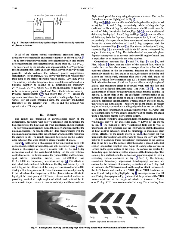
1268 PATEL ET AL. Fig. 5 of plasma actuators. flight envelope of the wing using the plasma actuators. The results from these tests are highlighted in Fig. 7. Figures 7a–7c show the effects of deflecting the aileron (indicated as A) by 1, 3, and 5 deg, respectively, while holding the flap (indicated as F) at 0 deg (no deflection) on the lift coefficient for 0 to 25 deg. In a similar fashion, Figs. 7d–7f show the effects of deflecting the flap by 1, 3 and 5 deg, and Figs. 7g–7i show the effects of deflecting both the flap and aileron together by 1, 3, and 5 deg, respectively. No appreciable effects are observed in the aerodynamic forces for aileron deflection of 1 and 3 deg compared with the baseline case (see Figs. 7a and 7b). For aileron deflection of 5 deg, shown in Fig. 7c, a noticeable shift in the lift curve is observed for angles of attack up to 15 deg. This is the classical response of a plane flap that corresponds to an increase in the zero-lift angle of attack that is equivalent to an increase in the wing camber. Comparisons between Figs. 7a and 7d, Figs. 7b and 7e, and Figs. 7c and 7f show that the effect of the inboard flap, which is smaller in size than the aileron, is stronger than the effect of the outboard aileron on the lift generated. Because the flow remains nominally attached at low angles of attack, the effects of the flap and aileron are considerably stronger than those with high angles of attack, at which flow separation and LEV become dominant. This limits the effectiveness of both the flap and aileron at high angles of attack. The maximum effect is observed when both the flap and aileron are deflected simultaneously (see Figs. 7g–7i). The lift augmentation effects of both control surfaces are roughly additive. In general, a linear shift in the lift coefficient corresponding to an increase in the zero-lift angle of attack is observed at low angles of attack by deflecting the flap/aileron, whereas at high angles of attack, their effects are nonexistent. Therefore, for flight control at higher angles of attack, conventional trailing-edge devices are not suitable. This is the basis for applying plasma actuators on the 1303 wing; that is, to demonstrate how the control authority can be greatly enhanced using a hingeless plasma flow control system. The results from flow visualization tests conducted on a full-span wingmodelat5,10,and15degatRec 1:69105 areshown in Fig. 8. The purpose of flow visualization tests was to was to understand the flow structure over the 1303 wing so that the locations of flow control actuators could be optimized to maximize their control effects. For the results shown in Fig. 8, fluorescent oil was used on the leeward surface of the wing to reveal the LEV and VBD patterns by capturing traces (streaklines) formed due to the viscous drag of the flow near the surface, after the model is placed in the test section for a certain length of time. A pair of leading-edge vortices is formed on the upper surface of the wing. The vortices are created by the rolling up of the shear layer that separates at the leading edge. The rotating flow reattaches to the surface and separates again to form a secondary vortex, evidenced in Fig. 8 (left) by the limiting streaklines (secondary separation). Leading-edge vortices are evident by the presence of secondary separation at 5 deg, and no evidence of a VBD is observed. As the angle of attack is increased, the LEV bursts and results in a VBD. These VBD locations for 10 and 15 deg are highlighted in Fig. 8. A comparison of 10 and 15 deg photographs in Fig. 8 shows that the position of the VBD moves upstream as the angle of attack is increased. Above Example of short-duty-cycle ac input for the unsteady operation In all of the plasma control experiments presented here, the actuators were operated in an unsteady manner, as shown in Fig. 5. The ac carrier frequency supplied to the electrodes was 5 kHz and the ac voltage supplied to the electrodes was on the order of 3–12 kVpp . The power used by the actuator was approximately 2–4 W per linear foot of actuator span. In the unsteady mode, very short duty cycles are possible, which reduces the actuator power requirements significantly. For example, a 10% duty cycle provided results better than those of the steady operation, which used a 100% duty cycle. The unsteady actuator frequency fmod was determined based on a Strouhal number St scaling of a dimensionless frequency, F fmodc=U1 1, where fmod is the modulation frequency, c is the mean aerodynamic chord, and U1 is the freestream velocity. Previous measurements [19] had shown that F 1 causes the optimum conditions to reattach separated leading-edge flows on wings. For all cases presented here, the unsteady modulation frequency of the actuator was 166 Hz and the actuator was operated at a 10% duty cycle. III. Results The results are presented in chronological order of the experiments, beginning with flow visualization that documents the basic features of the flow over the wing at different angles of attack. The flow visualization results guided the design and placement of the plasma actuators. The results of the lift–drag measurements with the plasma actuators documented the optimum arrangement to maximize the change in lift. The results presented here focus on the leading- edge actuators that were effective at larger angles of attack. Figure 6 (left) shows a photograph of the wing trailing edge with conventional control surfaces, flap, and split ailerons. Figure 6 (right) shows a photograph of passive devices with 1-, 3-, and 5-deg deflections used in the wind-tunnel testing for the conventional control surfaces. The dimensions of the (inboard) flap and (outboard) split aileron (hereafter, aileron) are 0:1 0:04 m and 0:13 0:038 m, respectively, as shown in Fig. 2d. The effects of individual and combined deflection of the flap and aileron by 1, 3, and 5 deg on the lift forces of the wing were measured for 0 to 25 deg with a 1-deg increment. These tests were conducted primarily to provide a basis for comparison with the plasma actuator effects, to highlight the inadequacy of 1303 conventional control surfaces in providing control at high angles of attack and, ultimately, to demonstrate improvements in control authority and the operational deg, VBD occurs over most of the wing. The secondary flow Fig. 6 Photographs showing the trailing edge of the wing model with conventional flap/aileron control surfaces. f 15 0 deg Passive flap/aileron devices for deflection fl s la sp ap pl p l i it t - a a i i l l e e r r o o n n s s 1 deg 3 deg 5 degPDF Image | Plasma Actuators for Hingeless Aerodynamic Control of an Unmanned Air Vehicle
PDF Search Title:
Plasma Actuators for Hingeless Aerodynamic Control of an Unmanned Air VehicleOriginal File Name Searched:
Plasma_Actuators_for_Hingeless_Aerodynamic_Control.pdfDIY PDF Search: Google It | Yahoo | Bing
NFT (Non Fungible Token): Buy our tech, design, development or system NFT and become part of our tech NFT network... More Info
IT XR Project Redstone NFT Available for Sale: NFT for high tech turbine design with one part 3D printed counter-rotating energy turbine. Be part of the future with this NFT. Can be bought and sold but only one design NFT exists. Royalties go to the developer (Infinity) to keep enhancing design and applications... More Info
Infinity Turbine IT XR Project Redstone Design: NFT for sale... NFT for high tech turbine design with one part 3D printed counter-rotating energy turbine. Includes all rights to this turbine design, including license for Fluid Handling Block I and II for the turbine assembly and housing. The NFT includes the blueprints (cad/cam), revenue streams, and all future development of the IT XR Project Redstone... More Info
Infinity Turbine ROT Radial Outflow Turbine 24 Design and Worldwide Rights: NFT for sale... NFT for the ROT 24 energy turbine. Be part of the future with this NFT. This design can be bought and sold but only one design NFT exists. You may manufacture the unit, or get the revenues from its sale from Infinity Turbine. Royalties go to the developer (Infinity) to keep enhancing design and applications... More Info
Infinity Supercritical CO2 10 Liter Extractor Design and Worldwide Rights: The Infinity Supercritical 10L CO2 extractor is for botanical oil extraction, which is rich in terpenes and can produce shelf ready full spectrum oil. With over 5 years of development, this industry leader mature extractor machine has been sold since 2015 and is part of many profitable businesses. The process can also be used for electrowinning, e-waste recycling, and lithium battery recycling, gold mining electronic wastes, precious metals. CO2 can also be used in a reverse fuel cell with nafion to make a gas-to-liquids fuel, such as methanol, ethanol and butanol or ethylene. Supercritical CO2 has also been used for treating nafion to make it more effective catalyst. This NFT is for the purchase of worldwide rights which includes the design. More Info
NFT (Non Fungible Token): Buy our tech, design, development or system NFT and become part of our tech NFT network... More Info
Infinity Turbine Products: Special for this month, any plans are $10,000 for complete Cad/Cam blueprints. License is for one build. Try before you buy a production license. May pay by Bitcoin or other Crypto. Products Page... More Info
| CONTACT TEL: 608-238-6001 Email: greg@infinityturbine.com | RSS | AMP |