PDF Publication Title:
Text from PDF Page: 012
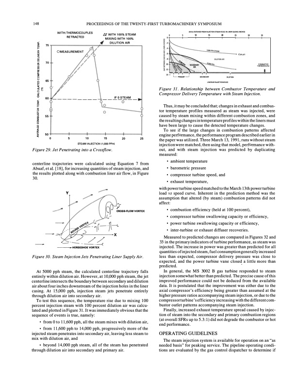
148 PROCEEDINGS OF THE TWENTY-FIRST TURBOMACHINERY SYMPOSIUM 65 60 55 � 500 �- Figure 31. Relationship between Combustor Temperature and Compressor Delivery Temperature with Steam Injection. Thus, it may be concluded that; changes in exhaust and combus tor temperature profiles measured as steam was injected, were caused by steam mixing within different combustion zones, and the resulting changes in temperature profiles within the liners must have been large to cause the detected temperature changes. To see if the large changes in combustion patterns affected engine performance, the performance program described earlier in the paper was utilized. Three March 13, 1991, runs without steam injection were matched, then using that model, performance with out, and with steam injection was predicted by duplicating measured: • ambient temperature • barometric pressure • compressor turbine speed, and • exhaust temperature, with power turbine speed matched to the March 13 th power turbine load vs speed curve. Inherent in the prediction method was the assumption that altered (by steam) combustion patterns did not affect: • combustion efficiency (held at 100 percent), • compressor turbine swallowing capacity or efficiency, • power turbine swallowing capacity or efficiency, • inter-turbine or exhaust diffuser recoveries. Measured to predicted changes are compared in Figures 32 and 33 in the primary indicators of turbine performance, as steam was injected. The increase in power was greater than predicted for all quantities of injected steam, fuel consumption generally increased less than expected, compressor delivery pressure was close to expected, and the power turbine vane closed a little more than predicted. In general, the MS 3002 B gas turbine responded to steam injection somewhat better than predicted. The precise cause of this improved performance could not be deduced from the available data. It is postulated that the improvement was either due to the axial compressor's efficiency being greater than assumed at the higher pressure ratios accompanying steam injection, or due to the compressor turbine's efficiency increasing with the different com bustor outlet patterns accompanying steam injection. Finally, increased exhaust temperature spread caused by injec tion of steam into the secondary and primary combustion regions (at overall SFRs up to 5.3:1) did not degrade the combustor or hot end performance. OPERATING GUIDELINES The steam injection system is available for operation on an "as needed basis" for peaking service. The pipeline operating condi tions are evaluated by the gas control dispatcher to determine if :> !'" u- � ------- WITH:THERMOCOUPLES RETRACTED OMEASUREMENT AT WITH 100% STEAM MIXING WITH 100% AXIAL DISTANCE FIIOM INJECTION STEAM HOLES IN LINER CASING IINCHESJ 10 15 20 0: ::;; ,_w > a:w �w 0 a: 70 f/)0 f/)wa:.. 0::; u 0w # DILUTION AIR IFOSTEAM L_ PRIMARY _j SECONDARY LINERAlR INJ£CTIONHOLES DILUTION (OF JET COMBUSTOR lliERMOCOUPlE 0: ::;; 0 �a: 0Iii :> "' ::;; 8w" �w 5 10 STEAM INJECTION 11,000 PPH) Figure 29. Jet Penetrating into a Crossflow. centerline trajectories were calculated using Equation 7 from Abuaf, et a!. [18], for increasing quantities of steam injection, and the results plotted along with combustion liner air flow, in Figure 30. 1 5 20 2 5 y -HORSESHOE VORTEX A'/ CROS8-FLOW VORTEX Figure 30. Steam Injection Jets Penetrating Liner Supply Air. At 5000 pph steam, the calculated centerline trajectory falls entirely within dilution air. However, at 10,000 pph steam, the jet centerline intersects the boundary between secondary and dilution air about four inches downstream of the injection holes in the liner casing. At 15,000 pph, injection steam jets penetrate entirely through dilution air into secondary air. To test this sequence, the temperature rise due to mixing 100 percent injection steam with 100 percent dilution air was calcu latedandplottedinFigure31.Itwasimmediatelyobviousthatthe sequence of events is true, namely: • from 0 to 11,600 pph, all the steam mixes with dilution air, • from 11,600 pph to 14,000 pph, progressively more of the injected steam penetrates into secondary air, leaving less steam to mix with dilution air, and • beyond 14,000 pph steam, all of the steam has penetrated through dilution air into secondary and primary air. ' 75 ---------PDF Image | STEAM INJECTION SYSTEM ON AN EARLY FRAME 3 GAS TURBINE IN A COMBINED CYCLE PIPELINE COMPRESSOR STATION
PDF Search Title:
STEAM INJECTION SYSTEM ON AN EARLY FRAME 3 GAS TURBINE IN A COMBINED CYCLE PIPELINE COMPRESSOR STATIONOriginal File Name Searched:
T21137-150.pdfDIY PDF Search: Google It | Yahoo | Bing
NFT (Non Fungible Token): Buy our tech, design, development or system NFT and become part of our tech NFT network... More Info
IT XR Project Redstone NFT Available for Sale: NFT for high tech turbine design with one part 3D printed counter-rotating energy turbine. Be part of the future with this NFT. Can be bought and sold but only one design NFT exists. Royalties go to the developer (Infinity) to keep enhancing design and applications... More Info
Infinity Turbine IT XR Project Redstone Design: NFT for sale... NFT for high tech turbine design with one part 3D printed counter-rotating energy turbine. Includes all rights to this turbine design, including license for Fluid Handling Block I and II for the turbine assembly and housing. The NFT includes the blueprints (cad/cam), revenue streams, and all future development of the IT XR Project Redstone... More Info
Infinity Turbine ROT Radial Outflow Turbine 24 Design and Worldwide Rights: NFT for sale... NFT for the ROT 24 energy turbine. Be part of the future with this NFT. This design can be bought and sold but only one design NFT exists. You may manufacture the unit, or get the revenues from its sale from Infinity Turbine. Royalties go to the developer (Infinity) to keep enhancing design and applications... More Info
Infinity Supercritical CO2 10 Liter Extractor Design and Worldwide Rights: The Infinity Supercritical 10L CO2 extractor is for botanical oil extraction, which is rich in terpenes and can produce shelf ready full spectrum oil. With over 5 years of development, this industry leader mature extractor machine has been sold since 2015 and is part of many profitable businesses. The process can also be used for electrowinning, e-waste recycling, and lithium battery recycling, gold mining electronic wastes, precious metals. CO2 can also be used in a reverse fuel cell with nafion to make a gas-to-liquids fuel, such as methanol, ethanol and butanol or ethylene. Supercritical CO2 has also been used for treating nafion to make it more effective catalyst. This NFT is for the purchase of worldwide rights which includes the design. More Info
NFT (Non Fungible Token): Buy our tech, design, development or system NFT and become part of our tech NFT network... More Info
Infinity Turbine Products: Special for this month, any plans are $10,000 for complete Cad/Cam blueprints. License is for one build. Try before you buy a production license. May pay by Bitcoin or other Crypto. Products Page... More Info
| CONTACT TEL: 608-238-6001 Email: greg@infinityturbine.com | RSS | AMP |