PDF Publication Title:
Text from PDF Page: 005
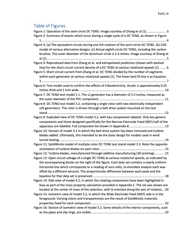
Table of Figures Figure 1: Operation of the semi-circle DC TENG. Image courtesy of Zhang et al [1]....................... 3 Figure 2: Summary of events which occur during a single cycle of a DC TENG, as shown in Figure 1. ................................................................................................................................................ 4 Figure 3: (a) The equivalent circuits during one full rotation of the semi-circle DC-TENG. (b) CAD model of various alternative designs. (c) Actual eighth-circle DC-TENG, including the carbon brushes. The outer diameter of the aluminum circle is 2.4 inches. Image courtesy of Zhang et al [1]........................................................................................................................................... 5 Figure 4: Reproduced data from Zhang et al. and extrapolated prediction (shown with dashed line) for the short circuit current density of a DC TENG at various rotational speeds [1]. ....... 6 Figure 5: Short circuit current from Zhang et al. DC TENG divided by the number of segments within each generator at various rotational speeds [1]. The linear best fit line is as Equation 1. ................................................................................................................................................ 7 Figure 6: Test model used to confirm the effects of triboelectricity. Acrylic is approximately 0.25 inches thick and 1 inch wide. .................................................................................................. 10 Figure 7: DC TENG test model 2.1. The s1 generator has a diameter of 2.5 inches, measured as the outer diameter of the PVC component............................................................................. 11 Figure 8: DC TENG test model 3.2, containing a single rotor with two electrically independent s20 generators. The rotor is driven through a belt drive system mounted on the test stand. ....................................................................................................................................... 12 Figure 9: Exploded view of DC TENG model 3.2, with key components labeled. Only key generic components and those designed specifically for the Narrow Electrode Fixed (NEF) half of the apparatus are labelled. Full component list shown in Appendix B. ........................................ 13 Figure 10: Version of model 3.2 in which the belt drive system has been removed and turbine blades added. Ultimately, this intended to be the basic design for models used in wind tunnel testing. ......................................................................................................................... 14 Figure 11: SolidWorks model of multiple-rotor DC TENG test stand model 3.3. Note the opposite orientation of turbine blades on each rotor. .......................................................................... 15 Figure 12: Turbine blades, manufactured through additive manufacturing (3D printing)............ 15 Figure 13: Open circuit voltage of a single DC-TENG at various rotational speeds, as indicated by the accompanying blocks on the right of the figure. Each data set contains a nearly uniform horizontal line which corresponds to a reading of zero volts, to elucidate analysis each was offset by a different amount. The proportionate difference between each peak and the baseline for that data set is preserved.................................................................................... 18 Figure 14: Side view of model 3.2, in which the rotating components have been highlighted in blue as part of the mass property calculation provided in Appendix E. The ink axis shown are located at the center of mass of the selection, with Ix oriented along the axis of rotation... 20 Figure 15: Isometric view of model 3.2, in which the Wide Electrode Fixed (WEF) side is in the foreground. Varying colors and transparencies are the result of SolidWorks materials properties fixed for each component. .................................................................................... 32 Figure 16: Section of isometric view of model 3.2. Some details of the interior components, such as the pipes and slip rings, are visible. .................................................................................... 33 Forti, iiiPDF Image | Triboelectric Turbines: Multi-Rotor Counter-Rotating Wind Turbine Utilizing Direct-Current Triboelectric Nanogenerators

PDF Search Title:
Triboelectric Turbines: Multi-Rotor Counter-Rotating Wind Turbine Utilizing Direct-Current Triboelectric NanogeneratorsOriginal File Name Searched:
Triboelectric-Turbines-Design-Construction-Multi-Rotor.pdfDIY PDF Search: Google It | Yahoo | Bing
NFT (Non Fungible Token): Buy our tech, design, development or system NFT and become part of our tech NFT network... More Info
IT XR Project Redstone NFT Available for Sale: NFT for high tech turbine design with one part 3D printed counter-rotating energy turbine. Be part of the future with this NFT. Can be bought and sold but only one design NFT exists. Royalties go to the developer (Infinity) to keep enhancing design and applications... More Info
Infinity Turbine IT XR Project Redstone Design: NFT for sale... NFT for high tech turbine design with one part 3D printed counter-rotating energy turbine. Includes all rights to this turbine design, including license for Fluid Handling Block I and II for the turbine assembly and housing. The NFT includes the blueprints (cad/cam), revenue streams, and all future development of the IT XR Project Redstone... More Info
Infinity Turbine ROT Radial Outflow Turbine 24 Design and Worldwide Rights: NFT for sale... NFT for the ROT 24 energy turbine. Be part of the future with this NFT. This design can be bought and sold but only one design NFT exists. You may manufacture the unit, or get the revenues from its sale from Infinity Turbine. Royalties go to the developer (Infinity) to keep enhancing design and applications... More Info
Infinity Supercritical CO2 10 Liter Extractor Design and Worldwide Rights: The Infinity Supercritical 10L CO2 extractor is for botanical oil extraction, which is rich in terpenes and can produce shelf ready full spectrum oil. With over 5 years of development, this industry leader mature extractor machine has been sold since 2015 and is part of many profitable businesses. The process can also be used for electrowinning, e-waste recycling, and lithium battery recycling, gold mining electronic wastes, precious metals. CO2 can also be used in a reverse fuel cell with nafion to make a gas-to-liquids fuel, such as methanol, ethanol and butanol or ethylene. Supercritical CO2 has also been used for treating nafion to make it more effective catalyst. This NFT is for the purchase of worldwide rights which includes the design. More Info
NFT (Non Fungible Token): Buy our tech, design, development or system NFT and become part of our tech NFT network... More Info
Infinity Turbine Products: Special for this month, any plans are $10,000 for complete Cad/Cam blueprints. License is for one build. Try before you buy a production license. May pay by Bitcoin or other Crypto. Products Page... More Info
| CONTACT TEL: 608-238-6001 Email: greg@infinityturbine.com | RSS | AMP |