PDF Publication Title:
Text from PDF Page: 099
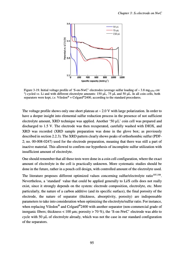
Chapter 3: S8 electrode on NwC Figure 3-19. Initial voltage profile of ‘S-on-NwC’ electrodes (average sulfur loading of ~ 3.8 mgsulfur cm- 2) cycled vs. Li and with different electrolyte amounts: 150 μL, 75 μL and 50 μL. In all coin cells, both separators were kept, i.e. Viledon® + Celgard®2400, according to the standard procedures. The voltage profile shows only one short plateau at ~ 2.0 V with large polarization. In order to have a deeper insight into elemental sulfur reduction process in the presence of not sufficient electrolyte amount, XRD technique was applied. Another ‘50 μL’ coin cell was prepared and discharged to 1.5 V. The electrode was then recuperated, carefully washed with DIOX, and XRD was recorded (XRD sample preparation was done in the glove box; as previously described in section 2.2.3). The XRD pattern clearly shows peaks of orthorhombic sulfur (PDF- 2; no. 00-008-0247) used for the electrode preparation, meaning that there was still a part of inactive material. This allowed to confirm our hypothesis of incomplete sulfur utilization with insufficient amount of electrolyte. One should remember that all these tests were done in a coin cell configuration, where the exact amount of electrolyte in the cell is practically unknown. More systematic studies should be done in the future, rather in a pouch cell design, with controlled amount of the electrolyte used. The literature proposes different optimized values concerning sulfur/electrolyte ratio105,106. Nevertheless, a ‘standard’ value that could be applied generally to Li/S cells does not really exist, since it strongly depends on the system: electrode composition, electrolyte, etc. More particularly, the nature of a carbon additive (and its specific surface), the final porosity of the electrode, the nature of separator (thickness, absorptivity, porosity) are indispensable parameters to take into consideration when optimizing the electrolyte/sulfur ratio. For instance, when replacing Viledon® and Celgard®2400 with another separator (non-commercial grade of inorganic fibers; thickness < 100 μm; porosity > 70 %), the ‘S-on-NwC’ electrode was able to cycle with 50 μL of electrolyte already, which was not the case in our standard configuration of the separators. 95PDF Image | Accumulateur Lithium Soufre
PDF Search Title:
Accumulateur Lithium SoufreOriginal File Name Searched:
WALUS_2015_archivage.pdfDIY PDF Search: Google It | Yahoo | Bing
Sulfur Deposition on Carbon Nanofibers using Supercritical CO2 Sulfur Deposition on Carbon Nanofibers using Supercritical CO2. Gamma sulfur also known as mother of pearl sulfur and nacreous sulfur... More Info
CO2 Organic Rankine Cycle Experimenter Platform The supercritical CO2 phase change system is both a heat pump and organic rankine cycle which can be used for those purposes and as a supercritical extractor for advanced subcritical and supercritical extraction technology. Uses include producing nanoparticles, precious metal CO2 extraction, lithium battery recycling, and other applications... More Info
| CONTACT TEL: 608-238-6001 Email: greg@infinityturbine.com | RSS | AMP |