PDF Publication Title:
Text from PDF Page: 102
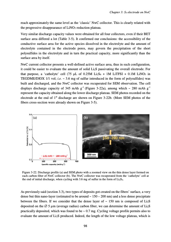
reach approximately the same level as the ‘classic’ NwC collector. This is clearly related with the progressive disappearance of LiNO3 reduction plateau. Very similar discharge capacity values were obtained for all four collectors, even if their BET surface area differed a lot (Table 3-5). It confirmed our conclusions: the accessibility of the conductive surface area for the active species dissolved in the electrolyte and the amount of electrolyte contained in the electrode pores, may govern the precipitation of the short polysulfides in the electrolyte and in turn the practical capacity, more significantly than the surface area by itself. NwC current collector presents a well-defined active surface area, thus in such configuration, it could be easier to evaluate the amount of solid Li2S passivating the overall electrode. For that purpose, a ‘catholyte’ cell (75 μL of 0.25M Li2S6 + 1M LiTFSI + 0.1M LiNO3 in TEGDME/DIOX 1/1 vol; i.e. ~ 3.6 mg of sulfur introduced in the form of polysulfides) was built and discharged, and the NwC collector was recuperated for SEM observation. The cell displays discharge capacity of 345 mAh g-1 (Figure 3-22a), among which ~ 280 mAh g-1 represent the capacity obtained along the lower discharge plateau. SEM photos recorded on the electrode at the end of 1st discharge are shown on Figure 3-22b. (More SEM photos of the fibers cross-section were already shown on Figure 3-5). (a) (b) Figure 3-22. Discharge profile (a) and SEM photo with a zoomed view on the thin dense layer formed on each carbon fiber of NwC collector (b). The NwC collector was recuperated from the ‘catholyte’ cell at the end of initial discharge, when cycling with 3.6 mg of sulfur in the form of Li2S4. As previously said (section 3.3), two types of deposits got created on the fibers’ surface, a very dense but thin nano-layer (estimated to be around ~ 150 – 200 nm) and a less dense precipitate between the fibers. If we consider that the dense layer of ~ 150 nm is composed of Li2S deposited on the ∅ 5 μm (average radius) carbon fiber, we can determine the amount of Li2S practically deposited, which was found to be ~ 0.7 mg. Cycling voltage profile permits also to evaluate the amount of Li2S produced. Indeed, the length of the low voltage plateau, which is Chapter 3: S8 electrode on NwC 98PDF Image | Accumulateur Lithium Soufre
PDF Search Title:
Accumulateur Lithium SoufreOriginal File Name Searched:
WALUS_2015_archivage.pdfDIY PDF Search: Google It | Yahoo | Bing
Sulfur Deposition on Carbon Nanofibers using Supercritical CO2 Sulfur Deposition on Carbon Nanofibers using Supercritical CO2. Gamma sulfur also known as mother of pearl sulfur and nacreous sulfur... More Info
CO2 Organic Rankine Cycle Experimenter Platform The supercritical CO2 phase change system is both a heat pump and organic rankine cycle which can be used for those purposes and as a supercritical extractor for advanced subcritical and supercritical extraction technology. Uses include producing nanoparticles, precious metal CO2 extraction, lithium battery recycling, and other applications... More Info
| CONTACT TEL: 608-238-6001 Email: greg@infinityturbine.com | RSS | AMP |