PDF Publication Title:
Text from PDF Page: 006
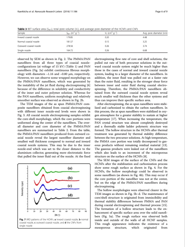
Kaerkitcha et al. Nanoscale Research Letters (2016) 11:186 Page 6 of 9 Table 3 BET surface area (SBET), total pore volume (VT), and average pore diameter of the HCNFs and CNFs Sample Inward coaxial nozzle Normal coaxial nozzle Outward coaxial nozzle Single nozzle SBET (m2 g−1) 179.85 181.57 278.56 164.72 VT (cm3 g−1) 0.20 0.15 0.26 0.26 Avg. pore diameter (nm) 4.48 3.25 3.74 6.68 observed by SEM as shown in Fig. 2. The PMMA/PAN nanofibers from all three types of coaxial nozzle- configurations (at voltage of 15 kV) (Table 1) and PAN nanofibers (Fig. 2a) exhibit continuous fibrous morph- ology with diameters ∼1.16 and ∼0.80 μm, respectively. However, we can observe some wrapped morphology on the PMMA/PAN nanofibers, which was generated by the instability of the jet fluid during electrospinning [6] because of the difference in solubility and conductivity of the inner and outer polymer solution. Whereas for the PAN nanofibers, uniform morphology and relatively smoother surface was observed as shown in Fig. 2b. The TEM images of the as spun PMMA/PAN com- posite nanofibers obtained from coaxial electrospinning with different inner nozzle-end levels were shown in Fig. 3. All coaxial nozzle electrospinning samples exhibit the core-shell morphology, which the core portions were uniformed along the center of the nanofibers. The over- all diameter and core diameter of the PMMA/PAN nanofibers are summarized in Table 2. From the table, the PMMA/PAN nanofibers produced from outward co- axial nozzle reveal the largest nanofiber diameter and smallest wall thickness compared to normal and inward coaxial nozzle systems. This may be due to the inner nozzle-end which was set to the closer distance to the aluminium collector, generating more electrostatic force that pulled the inner fluid out of the nozzle. At the fixed electrospinning flow rate of core and shell solutions, the pulled out rate of both precursor solutions in the out- ward coaxial nozzle system might be much higher than those in the cases of normal and inward coaxial nozzle system, leading to a larger diameter of the nanofibers. In addition, the inner fluid was pulled out at a faster rate than the outer fluid, resulting in the stronger shear force between inner and outer fluid during coaxial electro- spinning. Therefore, the PMMA/PAN nanofibers ob- tained from the outward coaxial nozzle system reveal much smaller wall thickness than the other systems and thus can improve their specific surface area. After electrospinning, the as spun nanofibers were stabi- lized and carbonized to obtain the carbon nanofibers. In this process, the as spun nanofibers were stabilized in oxy- gen atmosphere for a greater stability to sustain at higher temperature [17]. When increasing the temperature, the PAN crystal structure was almost completely destroyed and a thermally stable ladder polymeric structure was formed. The hollow structure in the HCNFs after thermal treatment was generated by thermal stability difference between the two precursor solutions. At high temperature, the PMMA core portion was totally decomposed to gas- eous products without remaining residual material [13]. The gaseous products were leaked out of the nanofibers which also leads to an increment of the microporous structure on the surface of the HCNFs [8]. The SEM images of the surface of the CNFs and the HCNFs after the stabilization and carbonization process show some rough surface as shown in Fig. 4. For the HCNFs, the hollow morphology could be observed in some nanofibers (as shown in Fig. 4b). This may occur if the core portion of the nanofiber was not at the center, but on the edge of the PMMA/PAN nanofibers during electrospinning. The hollow morphologies were observed clearer in the TEM images as shown in Fig. 5b–d. The maintenance of core/shell structure is originated from immiscibility and thermal stability differences between PMMA and PAN during coaxial electrospinning and thermal process [15]. The formation of a hollow structure leads to the en- hancement of specific surface area over the solid nanofi- bers (Fig. 5a). The rough surface was observed both inside and outside of the walls of all HCNF samples. This rough appearance indicates the existence of a mesoporous structure, which originated from Fig. 7 XRD patterns of the HCNFs. a inward coaxial nozzle, b normal coaxial nozzle, c outward coaxial nozzle, and d the CNFs from single nozzlePDF Image | carbon nanofibers obtained from coaxial electrospinning
PDF Search Title:
carbon nanofibers obtained from coaxial electrospinningOriginal File Name Searched:
s11671-016-1416-7.pdfDIY PDF Search: Google It | Yahoo | Bing
Sulfur Deposition on Carbon Nanofibers using Supercritical CO2 Sulfur Deposition on Carbon Nanofibers using Supercritical CO2. Gamma sulfur also known as mother of pearl sulfur and nacreous sulfur... More Info
CO2 Organic Rankine Cycle Experimenter Platform The supercritical CO2 phase change system is both a heat pump and organic rankine cycle which can be used for those purposes and as a supercritical extractor for advanced subcritical and supercritical extraction technology. Uses include producing nanoparticles, precious metal CO2 extraction, lithium battery recycling, and other applications... More Info
| CONTACT TEL: 608-238-6001 Email: greg@infinityturbine.com | RSS | AMP |