PDF Publication Title:
Text from PDF Page: 007
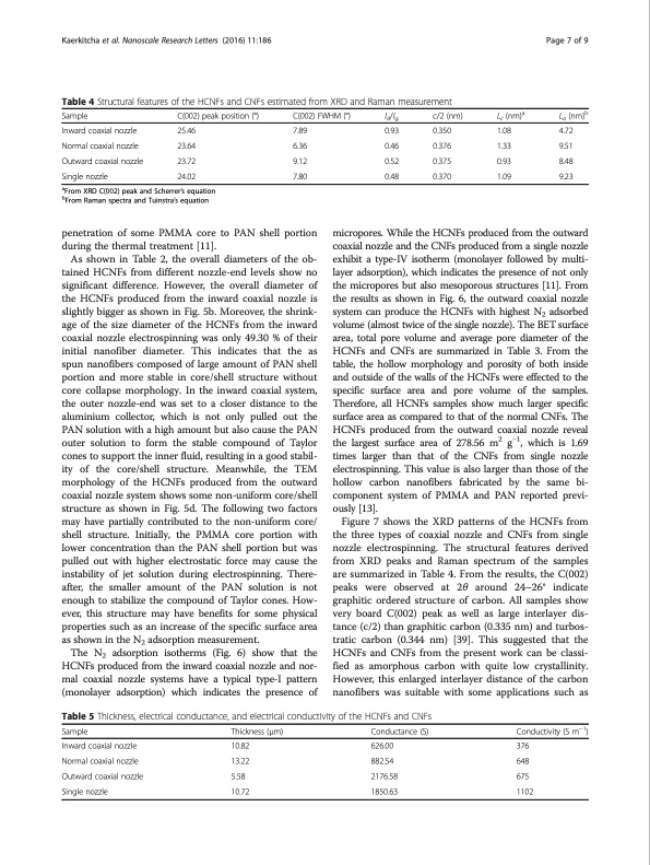
Kaerkitcha et al. Nanoscale Research Letters (2016) 11:186 Page 7 of 9 Table 4 Structural features of the HCNFs and CNFs estimated from XRD and Raman measurement Sample Inward coaxial nozzle Normal coaxial nozzle Outward coaxial nozzle Single nozzle C(002) peak position (°) 25.46 23.64 23.72 24.02 C(002) FWHM (°) Id/Ig c/2 (nm) 0.93 0.350 0.46 0.376 0.52 0.375 0.48 0.370 Lc (nm)a 1.08 1.33 0.93 1.09 La (nm)b 4.72 9.51 8.48 9.23 7.89 6.36 9.12 7.80 aFrom XRD C(002) peak and Scherrer’s equation bFrom Raman spectra and Tuinstra’s equation penetration of some PMMA core to PAN shell portion during the thermal treatment [11]. As shown in Table 2, the overall diameters of the ob- tained HCNFs from different nozzle-end levels show no significant difference. However, the overall diameter of the HCNFs produced from the inward coaxial nozzle is slightly bigger as shown in Fig. 5b. Moreover, the shrink- age of the size diameter of the HCNFs from the inward coaxial nozzle electrospinning was only 49.30 % of their initial nanofiber diameter. This indicates that the as spun nanofibers composed of large amount of PAN shell portion and more stable in core/shell structure without core collapse morphology. In the inward coaxial system, the outer nozzle-end was set to a closer distance to the aluminium collector, which is not only pulled out the PAN solution with a high amount but also cause the PAN outer solution to form the stable compound of Taylor cones to support the inner fluid, resulting in a good stabil- ity of the core/shell structure. Meanwhile, the TEM morphology of the HCNFs produced from the outward coaxial nozzle system shows some non-uniform core/shell structure as shown in Fig. 5d. The following two factors may have partially contributed to the non-uniform core/ shell structure. Initially, the PMMA core portion with lower concentration than the PAN shell portion but was pulled out with higher electrostatic force may cause the instability of jet solution during electrospinning. There- after, the smaller amount of the PAN solution is not enough to stabilize the compound of Taylor cones. How- ever, this structure may have benefits for some physical properties such as an increase of the specific surface area as shown in the N2 adsorption measurement. The N2 adsorption isotherms (Fig. 6) show that the HCNFs produced from the inward coaxial nozzle and nor- mal coaxial nozzle systems have a typical type-I pattern (monolayer adsorption) which indicates the presence of micropores. While the HCNFs produced from the outward coaxial nozzle and the CNFs produced from a single nozzle exhibit a type-IV isotherm (monolayer followed by multi- layer adsorption), which indicates the presence of not only the micropores but also mesoporous structures [11]. From the results as shown in Fig. 6, the outward coaxial nozzle system can produce the HCNFs with highest N2 adsorbed volume (almost twice of the single nozzle). The BET surface area, total pore volume and average pore diameter of the HCNFs and CNFs are summarized in Table 3. From the table, the hollow morphology and porosity of both inside and outside of the walls of the HCNFs were effected to the specific surface area and pore volume of the samples. Therefore, all HCNFs samples show much larger specific surface area as compared to that of the normal CNFs. The HCNFs produced from the outward coaxial nozzle reveal the largest surface area of 278.56 m2 g−1, which is 1.69 times larger than that of the CNFs from single nozzle electrospinning. This value is also larger than those of the hollow carbon nanofibers fabricated by the same bi- component system of PMMA and PAN reported previ- ously [13]. Figure 7 shows the XRD patterns of the HCNFs from the three types of coaxial nozzle and CNFs from single nozzle electrospinning. The structural features derived from XRD peaks and Raman spectrum of the samples are summarized in Table 4. From the results, the C(002) peaks were observed at 2θ around 24–26° indicate graphitic ordered structure of carbon. All samples show very board C(002) peak as well as large interlayer dis- tance (c/2) than graphitic carbon (0.335 nm) and turbos- tratic carbon (0.344 nm) [39]. This suggested that the HCNFs and CNFs from the present work can be classi- fied as amorphous carbon with quite low crystallinity. However, this enlarged interlayer distance of the carbon nanofibers was suitable with some applications such as Table 5 Thickness, electrical conductance, and electrical conductivity of the HCNFs and CNFs Sample Inward coaxial nozzle Normal coaxial nozzle Outward coaxial nozzle Single nozzle Thickness (μm) 10.82 13.22 5.58 10.72 Conductance (S) 626.00 882.54 2176.58 1850.63 Conductivity (S m−1) 376 648 675 1102PDF Image | carbon nanofibers obtained from coaxial electrospinning
PDF Search Title:
carbon nanofibers obtained from coaxial electrospinningOriginal File Name Searched:
s11671-016-1416-7.pdfDIY PDF Search: Google It | Yahoo | Bing
Sulfur Deposition on Carbon Nanofibers using Supercritical CO2 Sulfur Deposition on Carbon Nanofibers using Supercritical CO2. Gamma sulfur also known as mother of pearl sulfur and nacreous sulfur... More Info
CO2 Organic Rankine Cycle Experimenter Platform The supercritical CO2 phase change system is both a heat pump and organic rankine cycle which can be used for those purposes and as a supercritical extractor for advanced subcritical and supercritical extraction technology. Uses include producing nanoparticles, precious metal CO2 extraction, lithium battery recycling, and other applications... More Info
| CONTACT TEL: 608-238-6001 Email: greg@infinityturbine.com | RSS | AMP |