PDF Publication Title:
Text from PDF Page: 005
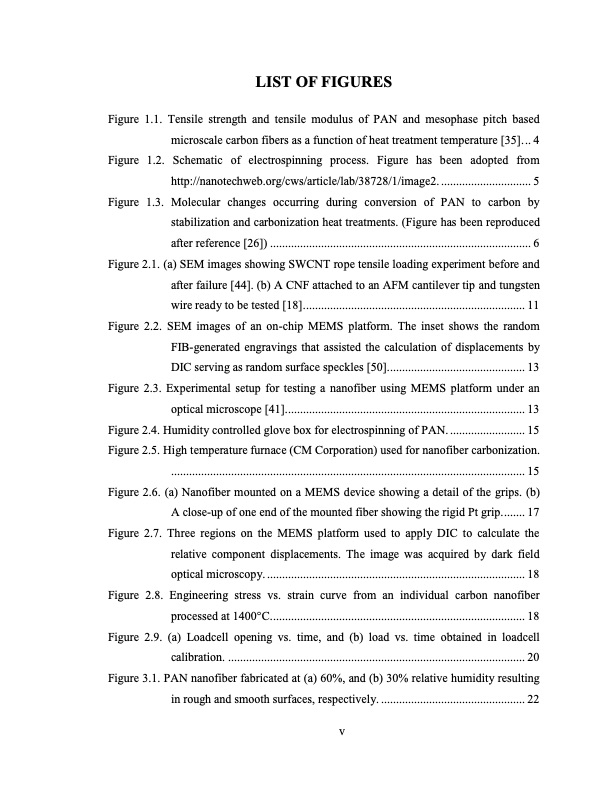
LIST OF FIGURES Figure 1.1. Tensile strength and tensile modulus of PAN and mesophase pitch based microscale carbon fibers as a function of heat treatment temperature [35]... 4 Figure 1.2. Schematic of electrospinning process. Figure has been adopted from http://nanotechweb.org/cws/article/lab/38728/1/image2. .............................. 5 Figure 1.3. Molecular changes occurring during conversion of PAN to carbon by stabilization and carbonization heat treatments. (Figure has been reproduced after reference [26]) ....................................................................................... 6 Figure 2.1. (a) SEM images showing SWCNT rope tensile loading experiment before and after failure [44]. (b) A CNF attached to an AFM cantilever tip and tungsten wire ready to be tested [18].......................................................................... 11 Figure 2.2. SEM images of an on-chip MEMS platform. The inset shows the random FIB-generated engravings that assisted the calculation of displacements by DIC serving as random surface speckles [50].............................................. 13 Figure 2.3. Experimental setup for testing a nanofiber using MEMS platform under an optical microscope [41]................................................................................ 13 Figure 2.4. Humidity controlled glove box for electrospinning of PAN. ......................... 15 Figure 2.5. High temperature furnace (CM Corporation) used for nanofiber carbonization. ...................................................................................................................... 15 Figure 2.6. (a) Nanofiber mounted on a MEMS device showing a detail of the grips. (b) A close-up of one end of the mounted fiber showing the rigid Pt grip........ 17 Figure 2.7. Three regions on the MEMS platform used to apply DIC to calculate the relative component displacements. The image was acquired by dark field optical microscopy. ...................................................................................... 18 Figure 2.8. Engineering stress vs. strain curve from an individual carbon nanofiber processed at 1400°C..................................................................................... 18 Figure 2.9. (a) Loadcell opening vs. time, and (b) load vs. time obtained in loadcell calibration. ................................................................................................... 20 Figure 3.1. PAN nanofiber fabricated at (a) 60%, and (b) 30% relative humidity resulting in rough and smooth surfaces, respectively. ................................................ 22 vPDF Image | HIGH STRENGTH CARBON NANOFIBERS DERIVED FROM ELECTROSPUN POLYACRYLONITRILE

PDF Search Title:
HIGH STRENGTH CARBON NANOFIBERS DERIVED FROM ELECTROSPUN POLYACRYLONITRILEOriginal File Name Searched:
4835609.pdfDIY PDF Search: Google It | Yahoo | Bing
Sulfur Deposition on Carbon Nanofibers using Supercritical CO2 Sulfur Deposition on Carbon Nanofibers using Supercritical CO2. Gamma sulfur also known as mother of pearl sulfur and nacreous sulfur... More Info
CO2 Organic Rankine Cycle Experimenter Platform The supercritical CO2 phase change system is both a heat pump and organic rankine cycle which can be used for those purposes and as a supercritical extractor for advanced subcritical and supercritical extraction technology. Uses include producing nanoparticles, precious metal CO2 extraction, lithium battery recycling, and other applications... More Info
| CONTACT TEL: 608-238-6001 Email: greg@infinityturbine.com | RSS | AMP |