PDF Publication Title:
Text from PDF Page: 020
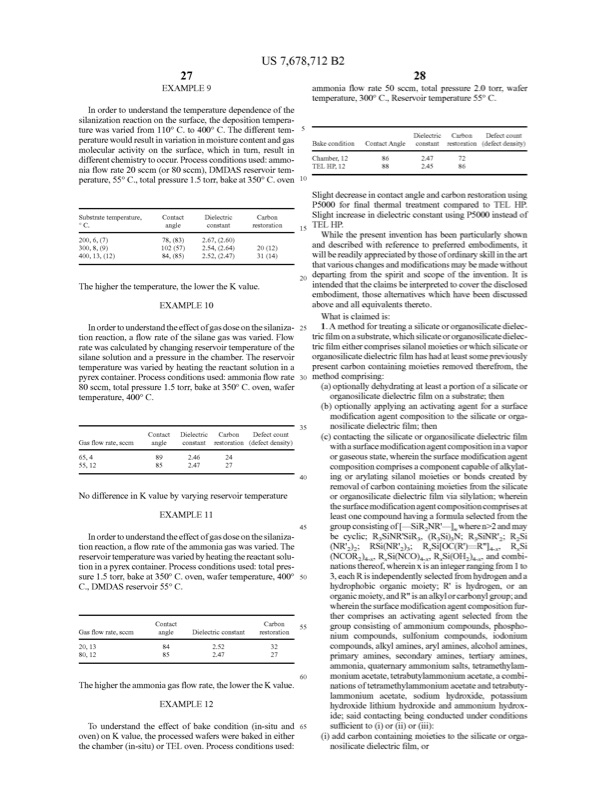
27 EXAMPLE 9 Inordertounderstandthetemperaturedependenceofthe silanizationreactionontheSurface,thedepositiontempera ture was varied from 110° C. to 400° C. The different tem peraturewouldresultinvariationinmoisturecontentandgas molecularactivityontheSurface,whichinturn,resultin diferentchemistrytoocur.Processconditionsused:ammo niaflowrate20sccm(or80sccm),DMDAS reservoirtem perature,55°C.,totalpressure1.5tor,bakeat350°C.oven Substratetemperature, Contact Dielectric Carbon 28 ammoniaflowrate50sccm,totalpressure2.0tor,wafer temperature,300°C.Reservoirtemperature55°C. Dielectric Carbon Defectcount Bakecondition ContactAngle constant restoration (defectdensity) oC. 200,6,(7) 300,8,(9) 400,13,(12) angle constant restoration 78,(83) 2.67,(2.60) 102(57) 2.54,(2.64) 20(12) 84,(85) 2.52,(2.47) 31(14) 10 15 Slightdecreaseincontactangleandcarbonrestorationusing P5000forfinalthermaltreatmentcomparedtoTEL HP. SlightincreaseindielectricconstantusingP5000insteadof TELHP. Whilethepresentinventionhasbeenparticularlyshown anddescribedwithreferencetopreferedembodiments,it wilbereadilyappreciatedbythoseofordinaryskilintheart thatvariouschangesandmodificationsmaybemadewithout departingfromthespiritandscopeoftheinvention.Itis intendedthattheclaimsbeinterpretedtocoverthedisclosed embodiment,thosealternativeswhichhavebeendiscussed aboveandalequivalentsthereto. What isclaimed is: 1.Amethodfortreatingasilicateororganosilicatedielec tricfilmonasubstrate,whichsilicateororganosilicatedielec tricfilmeithercomprisessilanolmoietiesorwhichsilicateor organosilicatedielectricfilmhashadatleastsomepreviously presentcarboncontainingmoietiesremovedtherefrom,the methodcomprising: (a)optionalydehydratingatleastaportionofasilicateor organosilicatedielectricfilmonasubstrate;then (b)optionalyapplyinganactivatingagentforaSurface modificationagentcompositiontothesilicateororga nosilicatedielectricfilm;then (c)contactingthesilicateororganosilicatedielectricfilm withaSurfacemodificationagentcompositioninavapor orgaseousstate,whereintheSurfacemodificationagent compositioncomprisesacomponentcapableofalkylat ingorarylatingsilanolmoietiesorbondscreatedby removalofcarboncontainingmoietiesfromthesilicate ororganosilicatedielectricfilmviasilylation;wherein theSurfacemodificationagentcompositioncomprisesat leastonecompoundhavingaformulaselectedfromthe groupconsistingof SiRNR' ,wheren>2andmay becyclic;RSiNR'SiR (RSi)N;RSiNR';RSi (NR'); RSi(NR'); RSiOC(R)—R"), RSi (NCOR), RSi(NCO), RSi(OH), andcombi nationsthereof,whereinXisanintegerrangingfrom1to 3,eachRisindependentlyselectedfromhydrogenanda hydrophobicorganicmoiety;R ishydrogen,oran organicmoiety,andR"isanalkylorcarbonylgroup;and whereintheSurfacemodificationagentcompositionfur thercomprisesanactivatingagentselectedfromthe groupconsistingofammoniumcompounds,phospho nium compounds, Sulfonium compounds, iodonium compounds,alkylamines,arylamines,alcoholamines, primary amines, secondary amines, tertiary amines, ammonia,quaternaryammoniumsalts,tetramethylam moniumacetate,tetrabutylammoniumacetate,acombi nationsoftetramethylammoniumacetateandtetrabuty lammonium acetate, sodium hydroxide, potassium hydroxidelithiumhydroxideandammoniumhydrox ide;saidcontactingbeingconductedunderconditions suficientto(i)or(i)or(i): (i)addcarboncontainingmoietiestothesilicateororga nosilicatedielectricfilm,or Thehigherthetemperature,thelowertheKvalue. EXAMPLE 10 Inordertounderstandtheefectofgasdoseonthesilaniza tionreaction,aflowrateofthesilanegaswasvaried.Flow ratewascalculatedbychangingreservoirtemperatureofthe silanesolutionandapressureinthechamber.Thereservoir temperaturewasvariedbyheatingthereactantSolutionina pyrexcontainer.Processconditionsused:ammoniaflowrate30 80sccm,totalpressure1.5tor,bakeat350°C.oven,wafer temperature,400°C. Gasflowrate,scom 65,4 55,12 Contact Dielectric Carbon Defectcount angle constant restoration (defectdensity) 89 2.46 24 85 2.47 27 25 35 40 45 50 55 60 65 NodiferenceinKvaluebyvaryingreservoirtemperature EXAMPLE11 Inordertounderstandtheefectofgasdoseonthesilaniza tionreaction,aflowrateoftheammoniagaswasvaried.The reservoirtemperaturewasvariedbyheatingthereactantSolu tioninapyrexcontainer.Processconditionsused:totalpres sure1.5tor,bakeat350°C.oven,wafertemperature,400° C.,DMDAS reservoir55°C. Contact Gasflowrate,scom angle Dielectricconstant restoration 20,13 84 2.52 32 80,12 85 2.47 27 Thehighertheammoniagasflowrate,thelowertheKvalue. EXAMPLE 12 Tounderstandtheefectofbakecondition(in-situand oven)onKvalue,theprocessedwaferswerebakedineither thechamber(in-situ)orTELoven.Processconditionsused: US 7,678,712B2 Carbon Chamber,12 TEL HP,12 86 2.47 72 88 2.45 86PDF Image | VAPOR PHASE TREATMENT OF DELECTRIC MATERALS

PDF Search Title:
VAPOR PHASE TREATMENT OF DELECTRIC MATERALSOriginal File Name Searched:
US7678712.pdfDIY PDF Search: Google It | Yahoo | Bing
Sulfur Deposition on Carbon Nanofibers using Supercritical CO2 Sulfur Deposition on Carbon Nanofibers using Supercritical CO2. Gamma sulfur also known as mother of pearl sulfur and nacreous sulfur... More Info
CO2 Organic Rankine Cycle Experimenter Platform The supercritical CO2 phase change system is both a heat pump and organic rankine cycle which can be used for those purposes and as a supercritical extractor for advanced subcritical and supercritical extraction technology. Uses include producing nanoparticles, precious metal CO2 extraction, lithium battery recycling, and other applications... More Info
| CONTACT TEL: 608-238-6001 Email: greg@infinityturbine.com | RSS | AMP |