PDF Publication Title:
Text from PDF Page: 009
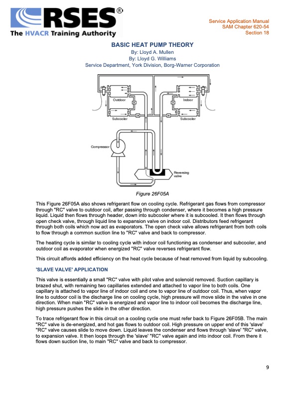
BASIC HEAT PUMP THEORY By: Lloyd A. Mullen By: Lloyd G. Williams Service Department, York Division, Borg-Warner Corporation Figure 26F05A This Figure 26F05A also shows refrigerant flow on cooling cycle. Refrigerant gas flows from compressor through "RC" valve to outdoor coil, after passing through condenser, where it becomes a high pressure liquid. Liquid then flows through header, down into subcooler where it is subcooled. It then flows through open check valve, through liquid line to expansion valve on indoor coil. Distributors feed refrigerant through both coils which now act as evaporators. The open check valve allows refrigerant from both coils to flow through a common suction line to "RC" valve and back to compressor. The heating cycle is similar to cooling cycle with indoor coil functioning as condenser and subcooler, and outdoor coil as evaporator when energized "RC" valve reverses refrigerant flow. This circuit affords added efficiency on the heat cycle because of heat removed from liquid by subcooling. 'SLAVE VALVE' APPLICATION This valve is essentially a small "RC" valve with pilot valve and solenoid removed. Suction capillary is brazed shut, with remaining two capillaries extended and attached to vapor line to both coils. One capillary is attached to vapor line of indoor coil and one to vapor line of outdoor coil. Thus, when vapor line to outdoor coil is the discharge line on cooling cycle, high pressure will move slide in the valve in one direction. When main "RC" valve is energized and vapor line to indoor coil becomes the discharge line, high pressure pushes the slide in the other direction. To trace refrigerant flow in this circuit on a cooling cycle one must refer back to Figure 26F05B. The main "RC" valve is de-energized, and hot gas flows to outdoor coil. High pressure on upper end of this 'slave' "RC" valve causes slide to move down. Liquid leaves the condenser and flows through 'slave' "RC" valve, to expansion valve. It then loops through the 'slave' "RC" valve again and into indoor coil. From there it flows down suction line, to main "RC" valve and back to compressor. Service Application Manual SAM Chapter 620-54 Section 18 9PDF Image | BASIC HEAT PUMP THEORY INTRO
PDF Search Title:
BASIC HEAT PUMP THEORY INTROOriginal File Name Searched:
620-54.pdfDIY PDF Search: Google It | Yahoo | Bing
CO2 Organic Rankine Cycle Experimenter Platform The supercritical CO2 phase change system is both a heat pump and organic rankine cycle which can be used for those purposes and as a supercritical extractor for advanced subcritical and supercritical extraction technology. Uses include producing nanoparticles, precious metal CO2 extraction, lithium battery recycling, and other applications... More Info
Heat Pumps CO2 ORC Heat Pump System Platform More Info
| CONTACT TEL: 608-238-6001 Email: greg@infinityturbine.com | RSS | AMP |