PDF Publication Title:
Text from PDF Page: 008
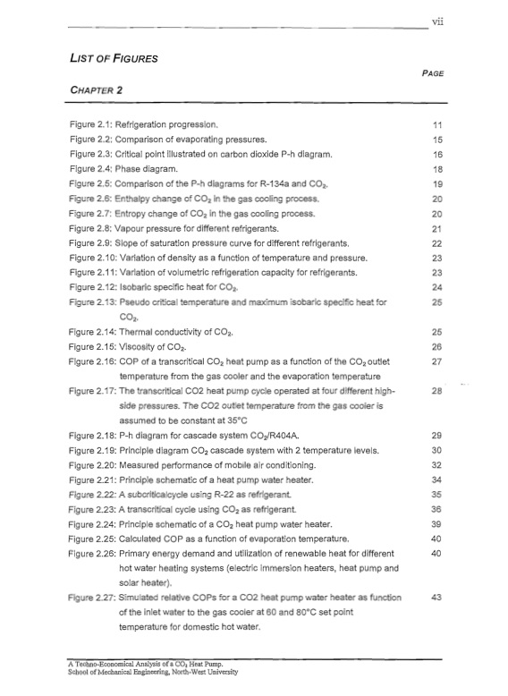
LIST OF FIGURES CHAPTER 2 Figure 2.1: Refrigeration progression. 11 Figure 2.2: Comparison of evaporating pressures. 15 Figure 2.3: Critical point illustrated on carbon dioxide P-h diagram. 16 Figure 2.4: Phase diagram. 18 Figure 2.5: Comparison of the P-h diagrams for R-134a and CO2, 19 Figure 2.6: Enthalpy change of CO2 in the gas cooling process. 20 Figure 2.7: Entropy change of CO2 in the gas cooling process. 20 Figure 2.8: Vapour pressure for different refrigerants. 21 Figure 2.9: Slope of saturation pressure curve for different refrigerants. 22 Figure 2.10: Variation of density as a function of temperature and pressure. 23 Figure 2.11: Variation of volumetric refrigeration capacity for refrigerants. 23 Figure 2.12: Isobaric specific heat for CO2• 24 Figure 2.13: Pseudo critical temperature and maximum isobaric specific heat for 25 CO2. Figure 2.14: Thermal conductivity of CO2• 25 Figure 2.15: Viscosity of CO2. 26 Figure 2.16: COP of a transcritical CO2 heat pump as a function of the CO2 outlet 27 temperature from the gas cooler and the evaporation temperature Figure 2.17: The transcritical C02 heat pump cycle operated at four different high- 28 side pressures. The C02 outlet temperature from the gas cooler is assumed to be constant at 35°C Figure 2.18: P-h diagram for cascade system C02/R404A. 29 Figure 2.19: Principle diagram CO2 cascade system with 2 temperature levels. 30 Figure 2.20: Measured performance of mobile air conditioning. 32 Figure 2.21: Principle schematic of a heat pump water heater. 34 Figure 2.22: A subcriticalcycle using R-22 as refrigerant. 35 Figure 2.23: A transcritical cycle using CO2 as refrigerant. 36 Figure 2.24: Principle schematic of a CO2 heat pump water heater. 39 Figure 2.25: Calculated COP as a function of evaporation temperature. 40 Figure 2.26: Primary energy demand and utilization of renewable heat for different 40 hot water heating systems (electric immersion heaters, heat pump and solar heater). Figure 2.27: Simulated relative COPs for a C02 heat pump water heater as fUnction 43 of the inlet water to the gas cooler at 60 and 80a C set point temperature for domestic hot water. A Techno-Economical Analysis of a C02 Heat Pump. School ofMechanical Engineering, North-West University - - - - - - - vii PAGEPDF Image | CO2 HEAT PUMP Analysis

PDF Search Title:
CO2 HEAT PUMP AnalysisOriginal File Name Searched:
co2-heat-pump-techno-analysis.pdfDIY PDF Search: Google It | Yahoo | Bing
CO2 Organic Rankine Cycle Experimenter Platform The supercritical CO2 phase change system is both a heat pump and organic rankine cycle which can be used for those purposes and as a supercritical extractor for advanced subcritical and supercritical extraction technology. Uses include producing nanoparticles, precious metal CO2 extraction, lithium battery recycling, and other applications... More Info
Heat Pumps CO2 ORC Heat Pump System Platform More Info
| CONTACT TEL: 608-238-6001 Email: greg@infinityturbine.com | RSS | AMP |