PDF Publication Title:
Text from PDF Page: 007
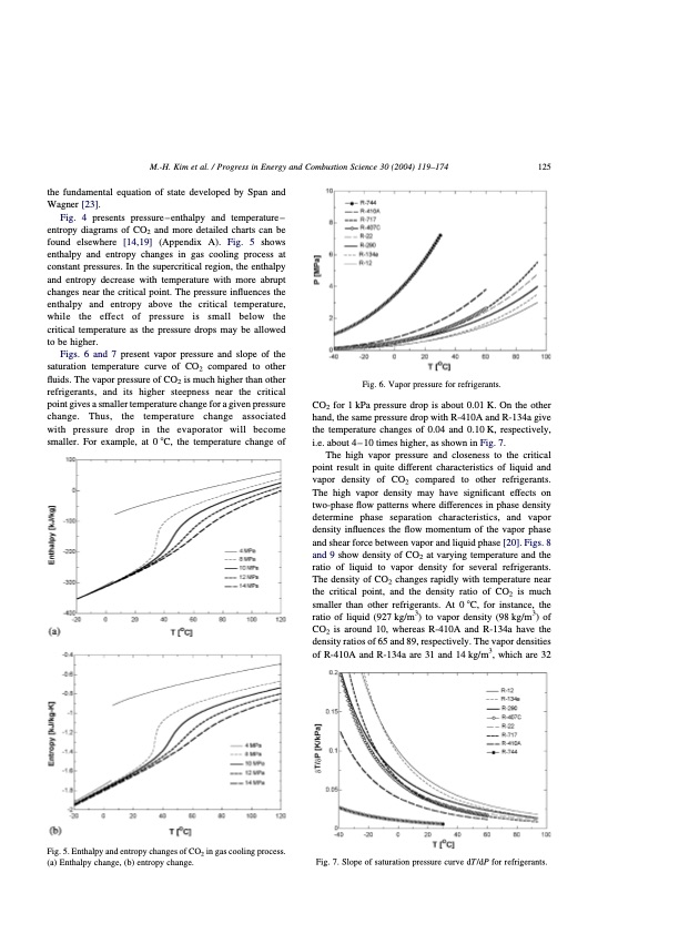
M.-H. Kim et al. / Progress in Energy and Combustion Science 30 (2004) 119–174 125 the fundamental equation of state developed by Span and Wagner [23]. Fig. 4 presents pressure–enthalpy and temperature– entropy diagrams of CO2 and more detailed charts can be found elsewhere [14,19] (Appendix A). Fig. 5 shows enthalpy and entropy changes in gas cooling process at constant pressures. In the supercritical region, the enthalpy and entropy decrease with temperature with more abrupt changes near the critical point. The pressure influences the enthalpy and entropy above the critical temperature, while the effect of pressure is small below the critical temperature as the pressure drops may be allowed to be higher. Figs. 6 and 7 present vapor pressure and slope of the saturation temperature curve of CO2 compared to other fluids. The vapor pressure of CO2 is much higher than other refrigerants, and its higher steepness near the critical point gives a smaller temperature change for a given pressure change. Thus, the temperature change associated with pressure drop in the evaporator will become smaller. For example, at 0 8C, the temperature change of Fig. 5. Enthalpy and entropy changes of CO2 in gas cooling process. (a) Enthalpy change, (b) entropy change. Fig. 6. Vapor pressure for refrigerants. CO2 for 1 kPa pressure drop is about 0.01 K. On the other hand, the same pressure drop with R-410A and R-134a give the temperature changes of 0.04 and 0.10 K, respectively, i.e. about 4 – 10 times higher, as shown in Fig. 7. The high vapor pressure and closeness to the critical point result in quite different characteristics of liquid and vapor density of CO2 compared to other refrigerants. The high vapor density may have significant effects on two-phase flow patterns where differences in phase density determine phase separation characteristics, and vapor density influences the flow momentum of the vapor phase and shear force between vapor and liquid phase [20]. Figs. 8 and 9 show density of CO2 at varying temperature and the ratio of liquid to vapor density for several refrigerants. The density of CO2 changes rapidly with temperature near the critical point, and the density ratio of CO2 is much smaller than other refrigerants. At 0 8C, for instance, the ratio of liquid (927 kg/m3) to vapor density (98 kg/m3) of CO2 is around 10, whereas R-410A and R-134a have the density ratios of 65 and 89, respectively. The vapor densities of R-410A and R-134a are 31 and 14 kg/m3, which are 32 Fig. 7. Slope of saturation pressure curve dT=dP for refrigerants.PDF Image | CO2 Vapor Compression Systems
PDF Search Title:
CO2 Vapor Compression SystemsOriginal File Name Searched:
co2-vapor-compression-systems.pdfDIY PDF Search: Google It | Yahoo | Bing
CO2 Organic Rankine Cycle Experimenter Platform The supercritical CO2 phase change system is both a heat pump and organic rankine cycle which can be used for those purposes and as a supercritical extractor for advanced subcritical and supercritical extraction technology. Uses include producing nanoparticles, precious metal CO2 extraction, lithium battery recycling, and other applications... More Info
Heat Pumps CO2 ORC Heat Pump System Platform More Info
| CONTACT TEL: 608-238-6001 Email: greg@infinityturbine.com | RSS | AMP |