PDF Publication Title:
Text from PDF Page: 021
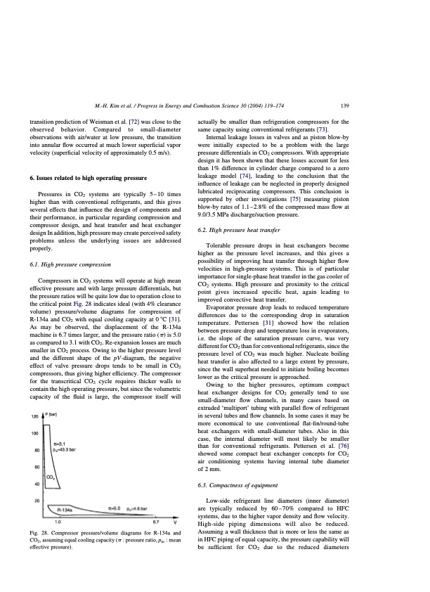
M.-H. Kim et al. / Progress in Energy and Combustion Science 30 (2004) 119–174 139 transition prediction of Weisman et al. [72] was close to the observed behavior. Compared to small-diameter observations with air/water at low pressure, the transition into annular flow occurred at much lower superficial vapor velocity (superficial velocity of approximately 0.5 m/s). 6. Issues related to high operating pressure Pressures in CO2 systems are typically 5 – 10 times higher than with conventional refrigerants, and this gives several effects that influence the design of components and their performance, in particular regarding compression and compressor design, and heat transfer and heat exchanger design In addition, high pressure may create perceived safety problems unless the underlying issues are addressed properly. 6.1. High pressure compression Compressors in CO2 systems will operate at high mean effective pressure and with large pressure differentials, but the pressure ratios will be quite low due to operation close to the critical point Fig. 28 indicates ideal (with 4% clearance volume) pressure/volume diagrams for compression of R-134a and CO2 with equal cooling capacity at 0 8C [31]. As may be observed, the displacement of the R-134a machine is 6.7 times larger, and the pressure ratio ðpÞ is 5.0 as compared to 3.1 with CO2. Re-expansion losses are much smaller in CO2 process. Owing to the higher pressure level and the different shape of the pV-diagram, the negative effect of valve pressure drops tends to be small in CO2 compressors, thus giving higher efficiency. The compressor for the transcritical CO2 cycle requires thicker walls to contain the high operating pressure, but since the volumetric capacity of the fluid is large, the compressor itself will Fig. 28. Compressor pressure/volume diagrams for R-134a and CO2, assuming equal cooling capacity (p : pressure ratio, pm : mean effective pressure). actually be smaller than refrigeration compressors for the same capacity using conventional refrigerants [73]. Internal leakage losses in valves and as piston blow-by were initially expected to be a problem with the large pressure differentials in CO2 compressors. With appropriate design it has been shown that these losses account for less than 1% difference in cylinder charge compared to a zero leakage model [74], leading to the conclusion that the influence of leakage can be neglected in properly designed lubricated reciprocating compressors. This conclusion is supported by other investigations [75] measuring piston blow-by rates of 1.1–2.8% of the compressed mass flow at 9.0/3.5 MPa discharge/suction pressure. 6.2. High pressure heat transfer Tolerable pressure drops in heat exchangers become higher as the pressure level increases, and this gives a possibility of improving heat transfer through higher flow velocities in high-pressure systems. This is of particular importance for single-phase heat transfer in the gas cooler of CO2 systems. High pressure and proximity to the critical point gives increased specific heat, again leading to improved convective heat transfer. Evaporator pressure drop leads to reduced temperature differences due to the corresponding drop in saturation temperature. Pettersen [31] showed how the relation between pressure drop and temperature loss in evaporators, i.e. the slope of the saturation pressure curve, was very different for CO2 than for conventional refrigerants, since the pressure level of CO2 was much higher. Nucleate boiling heat transfer is also affected to a large extent by pressure, since the wall superheat needed to initiate boiling becomes lower as the critical pressure is approached. Owing to the higher pressures, optimum compact heat exchanger designs for CO2 generally tend to use small-diameter flow channels, in many cases based on extruded ‘multiport’ tubing with parallel flow of refrigerant in several tubes and flow channels. In some cases it may be more economical to use conventional flat-fin/round-tube heat exchangers with small-diameter tubes. Also in this case, the internal diameter will most likely be smaller than for conventional refrigerants. Pettersen et al. [76] showed some compact heat exchanger concepts for CO2 air conditioning systems having internal tube diameter of 2 mm. 6.3. Compactness of equipment Low-side refrigerant line diameters (inner diameter) are typically reduced by 60 – 70% compared to HFC systems, due to the higher vapor density and flow velocity. High-side piping dimensions will also be reduced. Assuming a wall thickness that is more or less the same as in HFC piping of equal capacity, the pressure capability will be sufficient for CO2 due to the reduced diametersPDF Image | CO2 Vapor Compression Systems
PDF Search Title:
CO2 Vapor Compression SystemsOriginal File Name Searched:
co2-vapor-compression-systems.pdfDIY PDF Search: Google It | Yahoo | Bing
CO2 Organic Rankine Cycle Experimenter Platform The supercritical CO2 phase change system is both a heat pump and organic rankine cycle which can be used for those purposes and as a supercritical extractor for advanced subcritical and supercritical extraction technology. Uses include producing nanoparticles, precious metal CO2 extraction, lithium battery recycling, and other applications... More Info
Heat Pumps CO2 ORC Heat Pump System Platform More Info
| CONTACT TEL: 608-238-6001 Email: greg@infinityturbine.com | RSS | AMP |