PDF Publication Title:
Text from PDF Page: 026
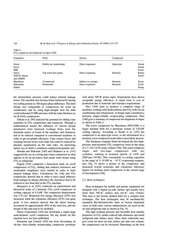
144 M.-H. Kim et al. / Progress in Energy and Combustion Science 30 (2004) 119–174 Table 2 CO2 compressor developments in Japan [106] Companies Denso Zexel MHI Sanyo TEPCO, Denso and CRIEPI Mayekawa Matsushita Daikin Field Mobile air-conditioning Tap water heat pump Commercial Residential System Direct expansion Direct expansion Indirect ice storage Direct expansion Compressor Open-type Hermetic Hermetic Hermetic Swash Swash Scroll Rotary Scroll Screw Scroll Swing the intermediate pressure could reduce internal leakage losses. The machine also became better balanced by having two rolling pistons in 180-degree phase difference. The shell design was comparable to compressors for room air conditioners, and by using high-strength steel the shell could withstand 25 MPa pressure with the same thickness as for R-410A compressors. Fukuta et al. [99] analyzed the potential for sliding vane machines in CO2 compression and expansion. Through a mathematical model the influence of various design parameters were analyzed. Leakage flows were the dominant source of losses in the machine, and clearances had to be reduced compared to conventional machines in order to get acceptable efficiency. Vane contact forces and resulting friction losses were high, but could be reduced by pressure equalization on the vane sides. An interesting option was to build a combined compressor/expander unit. Hiwada and Hokotani [100] and Ohakawa et al. [101] suggested the use of a swing type rotary compressor in what appears to be an air-source heat pump water heater using CO2 as refrigerant. Fagerli [102] conducted a theoretical study on scroll compression of CO2, finding that reduced clearances and axial/radial compliance were needed in order to limit internal leakage flows. Calculations for 134a and CO2 compressors showed that in order to have equal influence from leakage on energy efficiency the clearances had to be reduced to less than half in the CO2 machine. Hasegawa et al. [103] conducted an experimental and theoretical study of a hermetic CO2 scroll compressor of cooling capacity of 4.3 kW. The compressor displacement was 7.23 cm3. Relatively low energy efficiency (47%) was measured, while the volumetric efficiency (87%) was quite good. A loss analysis showed that the thrust bearing accounted for approximately 40% of the total loss, and the design of this part had to be modified. Denso Corporation [104] has developed a single-stage semi-hermetic scroll compressor, but any details on this machine have not been published. Baumann and Conzett [105] has been developing an oil-free four-cylinder reciprocating compressor prototype with about 500 W power input. Experiments have shown acceptable energy efficiency. A major issue is cost of production due to materials and tolerance requirements. S u ̈ s s [ 1 0 6 ] a i m s t o p r o d u c e a c o m p l e t e r a n g e o f machines working with hydrocarbons and CO2 both for air conditioning and refrigeration. A design study considered a hermetic single-cylinder reciprocating compressor. Su ̈ ss [106] gave a summary of compressor developments in Japan as shown in Table 2. The screw compressor by Mayekawa (MYCOM) is a larger machine built for a prototype system of 120 kW cooling capacity. According to Sasaki et al. [107] the compressor is an open-type screw, so the information on a hermetic screw compressor in the table is most likely an error. The European company Dorin developed the first high- pressure semi-hermetic CO2 compressor series in the range of 1.7 – 10.7 m3/h swept volume [108]. The series comprises single- and two-stage compressors with two cylinders, running at nominal speeds of 1450 and 2900 rpm (50 Hz). This corresponds to cooling capacities in the range of 3 – 25 kW at 2 10 8C evaporating tempera- ture. Fig. 33 shows a picture of the compressor, and measured overall isentropic and volumetric efficiency figures for medium sized compressors at the current stage of development [108]. 7.2. Heat exchangers Heat exchangers for mobile and unitary equipment are designed with a finned air-side surface and usually have more than 700 m2 surface area per m3 core volume. This ratio is the loosely defined limit for a compact heat exchanger. The heat exchangers may be mechanically expanded flat-fin/round-tube units or brazed aluminum cores, in both cases various enhancements are used on the air and refrigerant side as shown in Fig. 34. The high working pressure and favorable heat transfer properties of CO2 enable reduced tube diameters and small refrigerant-side surface areas. Since these reductions may give room for more air-side surface per unit core volume, the compactness can be increased. Depending on the heatPDF Image | CO2 Vapor Compression Systems
PDF Search Title:
CO2 Vapor Compression SystemsOriginal File Name Searched:
co2-vapor-compression-systems.pdfDIY PDF Search: Google It | Yahoo | Bing
CO2 Organic Rankine Cycle Experimenter Platform The supercritical CO2 phase change system is both a heat pump and organic rankine cycle which can be used for those purposes and as a supercritical extractor for advanced subcritical and supercritical extraction technology. Uses include producing nanoparticles, precious metal CO2 extraction, lithium battery recycling, and other applications... More Info
Heat Pumps CO2 ORC Heat Pump System Platform More Info
| CONTACT TEL: 608-238-6001 Email: greg@infinityturbine.com | RSS | AMP |