PDF Publication Title:
Text from PDF Page: 068
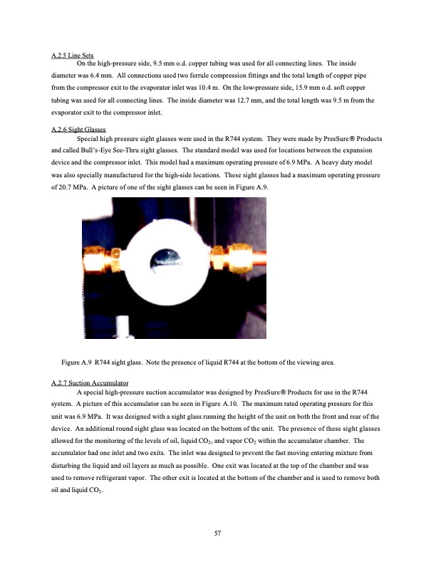
A.2.5 Line Sets On the high-pressure side, 9.5 mm o.d. copper tubing was used for all connecting lines. The inside diameter was 6.4 mm. All connections used two ferrule compression fittings and the total length of copper pipe from the compressor exit to the evaporator inlet was 10.4 m. On the low-pressure side, 15.9 mm o.d. soft copper tubing was used for all connecting lines. The inside diameter was 12.7 mm, and the total length was 9.5 m from the evaporator exit to the compressor inlet. A.2.6 Sight Glasses Special high pressure sight glasses were used in the R744 system. They were made by PresSure Products and called Bull’s-Eye See-Thru sight glasses. The standard model was used for locations between the expansion device and the compressor inlet. This model had a maximum operating pressure of 6.9 MPa. A heavy duty model was also specially manufactured for the high-side locations. These sight glasses had a maximum operating pressure of 20.7 MPa. A picture of one of the sight glasses can be seen in Figure A.9. Figure A.9 R744 sight glass. Note the presence of liquid R744 at the bottom of the viewing area. A.2.7 Suction Accumulator A special high-pressure suction accumulator was designed by PresSure Products for use in the R744 system. A picture of this accumulator can be seen in Figure A.10. The maximum rated operating pressure for this unit was 6.9 MPa. It was designed with a sight glass running the height of the unit on both the front and rear of the device. An additional round sight glass was located on the bottom of the unit. The presence of these sight glasses allowed for the monitoring of the levels of oil, liquid CO2, and vapor CO2 within the accumulator chamber. The accumulator had one inlet and two exits. The inlet was designed to prevent the fast moving entering mixture from disturbing the liquid and oil layers as much as possible. One exit was located at the top of the chamber and was used to remove refrigerant vapor. The other exit is located at the bottom of the chamber and is used to remove both oil and liquid CO2. 57PDF Image | Comparison of R744 and R410A
PDF Search Title:
Comparison of R744 and R410AOriginal File Name Searched:
CR039.pdfDIY PDF Search: Google It | Yahoo | Bing
CO2 Organic Rankine Cycle Experimenter Platform The supercritical CO2 phase change system is both a heat pump and organic rankine cycle which can be used for those purposes and as a supercritical extractor for advanced subcritical and supercritical extraction technology. Uses include producing nanoparticles, precious metal CO2 extraction, lithium battery recycling, and other applications... More Info
Heat Pumps CO2 ORC Heat Pump System Platform More Info
| CONTACT TEL: 608-238-6001 Email: greg@infinityturbine.com | RSS | AMP |