PDF Publication Title:
Text from PDF Page: 007
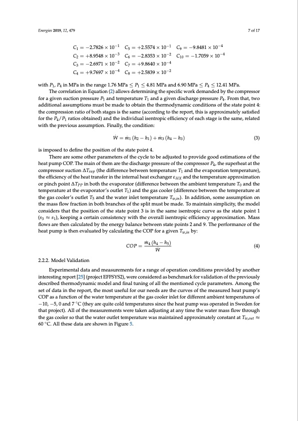
Energies 2019, 12, 479 7 of 17 C1 = −2.7826 × 10⁻¹ C2 = +8.9548 × 10⁻³ C3 = −2.6971 × 10⁻² C4 = +9.7697 × 10⁻⁴ C5 = +2.5574 × 10⁻¹ C6 = −2.8353 × 10⁻² C7 = +9.8640 × 10⁻⁴ C8 = +2.5839 × 10⁻² C9 = −9.8481 × 10⁻⁴ C10 = −1.7059 × 10⁻⁴ withP1,P4 inMPaintherange1.76MPa≤P1 ≤4.81MPaand6.90MPa≤P4 ≤12.41MPa. The correlation in Equation (2) allows determining the specific work demanded by the compressor for a given suction pressure P1 and temperature T1 and a given discharge pressure P4. From that, two additional assumptions must be made to obtain the thermodynamic conditions of the state point 4: the compression ratio of both stages is the same (according to the report, this is approximately satisfied for the P4/P1 ratios obtained) and the individual isentropic efficiency of each stage is the same, related with the previous assumption. Finally, the condition: W ̇ =m ̇1(h2−h1)+m ̇3(h4−h3) (3) is imposed to define the position of the state point 4. There are some other parameters of the cycle to be adjusted to provide good estimations of the heat pump COP. The main of them are the discharge pressure of the compressor P4, the superheat at the compressor suction ∆Tsup (the difference between temperature T1 and the evaporation temperature), the efficiency of the heat transfer in the internal heat exchanger εHX and the temperature approximation or pinch point ∆TPP in both the evaporator (difference between the ambient temperature T0 and the temperature at the evaporator’s outlet T1) and the gas cooler (difference between the temperature at the gas cooler’s outlet T5 and the water inlet temperature Tw,in). In addition, some assumption on the mass flow fraction in both branches of the split must be made. To maintain simplicity, the model considers that the position of the state point 3 is in the same isentropic curve as the state point 1 (s3 ≈ s1), keeping a certain consistency with the overall isentropic efficiency approximation. Mass flows are then calculated by the energy balance between state points 2 and 9. The performance of the heat pump is then evaluated by calculating the COP for a given Tw,in by: COP = m ̇ 4 (h4 − h5) (4) W ̇ 2.2.2. Model Validation Experimental data and measurements for a range of operation conditions provided by another interesting report [25] (project EFFSYS2), were considered as benchmark for validation of the previously described thermodynamic model and final tuning of all the mentioned cycle parameters. Among the set of data in the report, the most useful for our needs are the curves of the measured heat pump’s COP as a function of the water temperature at the gas cooler inlet for different ambient temperatures of −10, −5, 0 and 7 ◦C (they are quite cold temperatures since the heat pump was operated in Sweden for that project). All of the measurements were taken adjusting at any time the water mass flow through the gas cooler so that the water outlet temperature was maintained approximately constant at Tw,out ≈ 60 ◦C. All these data are shown in Figure 5.PDF Image | Comparison of Transcritical CO2 and Conventional Refrigerant Heat Pump

PDF Search Title:
Comparison of Transcritical CO2 and Conventional Refrigerant Heat PumpOriginal File Name Searched:
energies-12-00479.pdfDIY PDF Search: Google It | Yahoo | Bing
CO2 Organic Rankine Cycle Experimenter Platform The supercritical CO2 phase change system is both a heat pump and organic rankine cycle which can be used for those purposes and as a supercritical extractor for advanced subcritical and supercritical extraction technology. Uses include producing nanoparticles, precious metal CO2 extraction, lithium battery recycling, and other applications... More Info
Heat Pumps CO2 ORC Heat Pump System Platform More Info
| CONTACT TEL: 608-238-6001 Email: greg@infinityturbine.com | RSS | AMP |