PDF Publication Title:
Text from PDF Page: 004
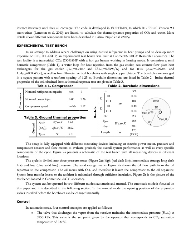
interact iteratively until they all converge. The code is developed in FORTRAN, to which REFPROP Version 9.1 subroutines (Lemmon et al. 2013) are linked, to calculate the thermodynamic properties of CO2 and water. More details about different components have been described in Eslami Nejad et al. (2015) EXPERIMENTAL TEST BENCH In an attempt to address recent challenges on using natural refrigerant in heat pumps and to develop more expertise on CO2 DX-GSHP, an experimental test bench was built at CanmetENERGY Research Laboratory. The test facility is a transcritical CO2 DX-GSHP with a hot gas bypass working in heating mode. It comprises a semi hermetic compressor (Table 1), a water loop for heat rejection from the gas cooler, two counter-flow plate heat exchangers for the gas cooler (AGC=0.74m2 and UAGC=0.3kW/K) and for IHE (AIHE=0.092m2 and UAIHE=0.1kW/K), as well as four 30-meter vertical boreholes with single copper U-tube. The boreholes are arranged in a square pattern with a uniform spacing of 6.25 m. Borehole dimensions are listed in Table 2. Insitu thermal properties of the soil obtained from a thermal response test are given in Table 3. Table 1. Compressor Nominal refrigeration capacity ton 1 Table 2. Borehole dimensions Nominal power input kW Compressor speed m3/h 1.36 1.12 rb U ID OD D ID OD 2D kgrout kpipe Length 3.9 0.64 cm 0.8 0.48 0.64 (4X30) Table 3. Ground thermal properties 2.3 0.8 Kground (𝜌𝜌𝑐𝑐𝑝𝑝)g Tground W/m/K 2.65 3 kJ/m /K 2862 W/m/K 400 m 120 °C 9.0 The setup is fully equipped with different measuring devices including an electric power meter, pressure and temperature sensors and flow meters to evaluate precisely the overall system performance as well as every specific components of the cycle. Figure 2a presents a schematic of the test bench with all measuring devices at different locations. The cycle is divided into three pressure zones (Figure 2a): high (red dash line), intermediate (orange long dash line) and low (blue solid line) pressure. The solid orange line in Figure 2a shows the oil flow path from the oil separator to the compressor. The oil mixes with CO2 and therefore it leaves the compressor to the oil separator. System heat transfer losses to the ambient is minimised through sufficient insulation. Figure 2b is the picture of the test bench located in CanmetENERGY laboratory. The system can be operated in two different modes; automatic and manual. The automatic mode is focused on this paper and it is described in the following section. In the manual mode the opening position of the expansion valves installed before the boreholes can be changed manually. Control In automatic mode, four control strategies are applied as follows: • The valve that discharges the vapor from the receiver maintains the intermediate pressure (Preceiver) at 3750 kPa. This value is the set point given by the operator that corresponds to CO2 saturation temperature of 2.8 °C. Ground Borehole CompressorPDF Image | Direct expansion ground source heat pump using R744
PDF Search Title:
Direct expansion ground source heat pump using R744Original File Name Searched:
oksd_igshpa_2017_Nejad.pdfDIY PDF Search: Google It | Yahoo | Bing
CO2 Organic Rankine Cycle Experimenter Platform The supercritical CO2 phase change system is both a heat pump and organic rankine cycle which can be used for those purposes and as a supercritical extractor for advanced subcritical and supercritical extraction technology. Uses include producing nanoparticles, precious metal CO2 extraction, lithium battery recycling, and other applications... More Info
Heat Pumps CO2 ORC Heat Pump System Platform More Info
| CONTACT TEL: 608-238-6001 Email: greg@infinityturbine.com | RSS | AMP |