PDF Publication Title:
Text from PDF Page: 009
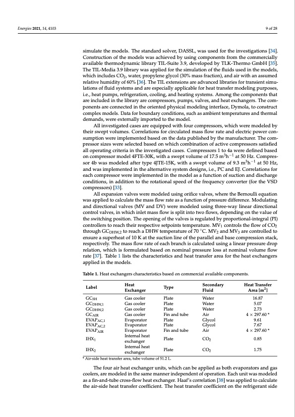
Energies 2021, 14, 4103 9 of 28 simulate the models. The standard solver, DASSL, was used for the investigations [34]. Construction of the models was achieved by using components from the commercially available thermodynamic library TIL-Suite 3.9, developed by TLK-Thermo GmbH [35]. The TIL-Media 3.9 library was applied for the simulation of the fluids used in the models, which includes CO2, water, propylene glycol (30% mass fraction), and air with an assumed relative humidity of 60% [36]. The TIL extensions are advanced libraries for transient simu- lations of fluid systems and are especially applicable for heat transfer modeling purposes, i.e., heat pumps, refrigeration, cooling, and heating systems. Among the components that are included in the library are compressors, pumps, valves, and heat exchangers. The com- ponents are connected in the oriented physical modeling interface, Dymola, to construct complex models. Data for boundary conditions, such as ambient temperatures and thermal demands, were externally imported to the model. All investigated cases are equipped with four compressors, which were modeled by their swept volumes. Correlations for circulated mass flow rate and electric power con- sumption were implemented based on the data published by the manufacturer. The com- pressor sizes were selected based on which combination of active compressors satisfied all operating criteria in the investigated cases. Compressors 1 to 4a were defined based on compressor model 4FTE-30K, with a swept volume of 17.5 m3h−1 at 50 Hz. Compres- sor 4b was modeled after type 4JTE-15K, with a swept volume of 9.3 m3h−1 at 50 Hz, and was implemented in the alternative system designs, i.e., PC and EJ. Correlations for each compressor were implemented in the model as a function of suction and discharge conditions, in addition to the rotational speed of the frequency converter (for the VSD compressors) [33]. All expansion valves were modeled using orifice valves, where the Bernoulli equation was applied to calculate the mass flow rate as a function of pressure difference. Modulating and directional valves (MV and DV) were modeled using three-way linear directional control valves, in which inlet mass flow is split into two flows, depending on the value of the switching position. The opening of the valves is regulated by proportional-integral (PI) controllers to reach their respective setpoints temperature. MV1 controls the flow of CO2 through GCDHW,2 to reach a DHW temperature of 70 ◦C. MV2 and MV3 are controlled to ensure a superheat of 10 K at the suction line of the parallel and base compression stack, respectively. The mass flow rate of each branch is calculated using a linear pressure drop relation, which is formulated based on nominal pressure loss at nominal volume flow rate [37]. Table 1 lists the characteristics and heat transfer area for the heat exchangers applied in the models. Table 1. Heat exchangers characteristics based on commercial available components. Secondary Heat Transfer Fluid Area [m2 ] Water 16.87 Water 5.07 Water 2.73 Air 4 × 297.60 * Glycol 9.61 Glycol 7.67 Air 4 × 297.60 * CO2 0.85 CO2 1.75 The four air heat exchanger units, which can be applied as both evaporators and gas coolers, are modeled in the same manner independent of operation. Each unit was modeled as a fin-and-tube cross-flow heat exchanger. Haaf’s correlation [38] was applied to calculate the air-side heat transfer coefficient. The heat transfer coefficient on the refrigerant side Label Heat Exchanger GCSH Gas cooler GCDHW,1 Gas cooler GCDHW,2 Gas cooler GCAIR Gas cooler EVAPAC,1 Evaporator EVAPAC,2 Evaporator EVAPAIR Evaporator IHX1 Internal heat exchanger IHX2 Internal heat Type Plate Plate Plate Fin and tube Plate Plate Fin and tube Plate Plate * Air-side heat transfer area, tube volume of 51.2 L. exchangerPDF Image | Evaluation of Integrated Concepts with CO2 for Heating
PDF Search Title:
Evaluation of Integrated Concepts with CO2 for HeatingOriginal File Name Searched:
energies-14-04103-v2.pdfDIY PDF Search: Google It | Yahoo | Bing
CO2 Organic Rankine Cycle Experimenter Platform The supercritical CO2 phase change system is both a heat pump and organic rankine cycle which can be used for those purposes and as a supercritical extractor for advanced subcritical and supercritical extraction technology. Uses include producing nanoparticles, precious metal CO2 extraction, lithium battery recycling, and other applications... More Info
Heat Pumps CO2 ORC Heat Pump System Platform More Info
| CONTACT TEL: 608-238-6001 Email: greg@infinityturbine.com | RSS | AMP |