PDF Publication Title:
Text from PDF Page: 074
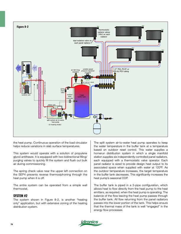
Figure 8-2 TRV thermostatic radiator valves (TRV) on each radiator TRV (P2) air vent w/ check TRV dual isolation valve on each panel radiator TRV TRV TRV outside air outside air air/dirt/mag separator outdoor reset controller variable-speed pressure-regulated circulator 1/2" PEX, PE-RT or PEX-AL-PEX tubing rev. valve outdoor unit spring check valve split system air-to-water heat pump (in heating mode) indoor unit 3-pipe buffer tank (P1) condenser heating mode compressor TXV evaporator outside inside refrigerant line set the heat pump. Continuous operation of the load circulator helps reduce variations in slab surface temperatures. This system would operate with a solution of propylene glycol antifreeze. It is equipped with two bidirectional filling/ purging valves to quickly fill the system and flush out bulk air during commissioning. The spring check valve near the upper left connection on the SEP4 prevents reverse thermosiphoning through the heat pump when it is off. The entire system can be operated from a simple wall thermostat. SYSTEM #2 The system shown in Figure 8-2, is another “heating only” application, but with extensive zoning of the heating distribution system. The split system air-to-water heat pump operates to keep the water temperature in the buffer tank at a temperature based on outdoor reset control. This water supplies a homerun distribution system in which a single manifold station supplies six independently controlled panel radiators, each equipped with a thermostatic valve operator. Each panel radiator is sized to provide design heat output to its associated space when supplied with water at 120oF. As the outdoor temperature increases, the target temperature in the buffer tank decreases. This significantly increases the heat pump’s seasonal COP. The buffer tank is piped in a 3-pipe configuration, which allows heat to flow directly from the heat pump to the heat emitters, as required, when the heat pump is operating. The balance of the flow leaving the heat pump passes through the buffer tank. All flow returning from the panel radiators passes into the lower portion of the tank. This helps ensure that the thermal mass of the tank is well “engaged” in the energy flow processes. 74PDF Image | Heat Pump Systems 2020
PDF Search Title:
Heat Pump Systems 2020Original File Name Searched:
idronics_27_na.pdfDIY PDF Search: Google It | Yahoo | Bing
CO2 Organic Rankine Cycle Experimenter Platform The supercritical CO2 phase change system is both a heat pump and organic rankine cycle which can be used for those purposes and as a supercritical extractor for advanced subcritical and supercritical extraction technology. Uses include producing nanoparticles, precious metal CO2 extraction, lithium battery recycling, and other applications... More Info
Heat Pumps CO2 ORC Heat Pump System Platform More Info
| CONTACT TEL: 608-238-6001 Email: greg@infinityturbine.com | RSS | AMP |