PDF Publication Title:
Text from PDF Page: 020
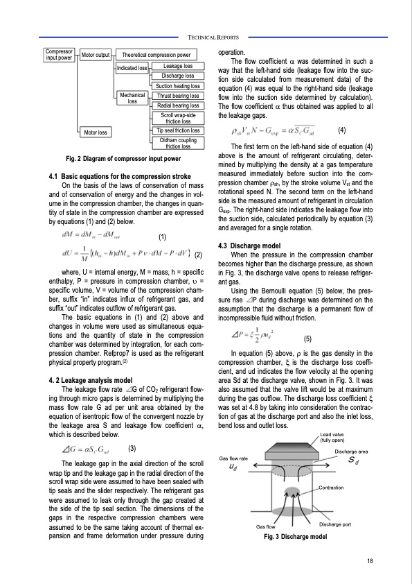
Compressor input power TECHNICAL REPORTS Motor output Theoretical compression power Leakage loss Indicated loss Discharge loss Suction heating loss Mechanical loss Thrust bearing loss Radial bearing loss Scroll wrap-side friction loss Motor loss Fig. 2 Diagram of compressor input power 4.1 Basic equations for the compression stroke On the basis of the laws of conservation of mass and of conservation of energy and the changes in vol- ume in the compression chamber, the changes in quan- tity of state in the compression chamber are expressed by equations (1) and (2) below. (1) (2) where, U = internal energy, M = mass, h = specific enthalpy, P = pressure in compression chamber, υ = specific volume, V = volume of the compression cham- ber, suffix “in” indicates influx of refrigerant gas, and suffix “out” indicates outflow of refrigerant gas. The basic equations in (1) and (2) above and changes in volume were used as simultaneous equa- tions and the quantity of state in the compression chamber was determined by integration, for each com- pression chamber. Refprop7 is used as the refrigerant physical property program.(2) 4. 2 Leakage analysis model The leakage flow rate G of CO2 refrigerant flow- ing through micro gaps is determined by multiplying the mass flow rate G ad per unit area obtained by the equation of isentropic flow of the convergent nozzle by the leakage area S and leakage flow coefficient α, which is described below. (3) The leakage gap in the axial direction of the scroll wrap tip and the leakage gap in the radial direction of the scroll wrap side were assumed to have been sealed with tip seals and the slider respectively. The refrigerant gas were assumed to leak only through the gap created at the side of the tip seal section. The dimensions of the gaps in the respective compression chambers were assumed to be the same taking account of thermal ex- pansion and frame deformation under pressure during operation. The flow coefficient α was determined in such a way that the left-hand side (leakage flow into the suc- tion side calculated from measurement data) of the equation (4) was equal to the right-hand side (leakage flow into the suction side determined by calculation). The flow coefficient α thus obtained was applied to all the leakage gaps. (4) The first term on the left-hand side of equation (4) above is the amount of refrigerant circulating, deter- mined by multiplying the density at a gas temperature measured immediately before suction into the com- pression chamber ρsh, by the stroke volume Vst and the rotational speed N. The second term on the left-hand side is the measured amount of refrigerant in circulation Gexp. The right-hand side indicates the leakage flow into the suction side, calculated periodically by equation (3) and averaged for a single rotation. 4.3 Discharge model When the pressure in the compression chamber becomes higher than the discharge pressure, as shown in Fig. 3, the discharge valve opens to release refriger- ant gas. Using the Bernoulli equation (5) below, the pres- sure rise P during discharge was determined on the assumption that the discharge is a permanent flow of incompressible fluid without friction. (5) In equation (5) above, ρ is the gas density in the compression chamber, ξ is the discharge loss coeffi- cient, and ud indicates the flow velocity at the opening area Sd at the discharge valve, shown in Fig. 3. It was also assumed that the valve lift would be at maximum during the gas outflow. The discharge loss coefficient ξ was set at 4.8 by taking into consideration the contrac- tion of gas at the discharge port and also the inlet loss, bend loss and outlet loss. Tip seal friction loss Oldham coupling friction loss Lead valve (fully open) Gas flow rate Discharge area Contraction Discharge port Gas flow Fig. 3 Discharge model 18PDF Image | Heat Pump with Natural Refrigerants 3041
PDF Search Title:
Heat Pump with Natural Refrigerants 3041Original File Name Searched:
vol120.pdfDIY PDF Search: Google It | Yahoo | Bing
CO2 Organic Rankine Cycle Experimenter Platform The supercritical CO2 phase change system is both a heat pump and organic rankine cycle which can be used for those purposes and as a supercritical extractor for advanced subcritical and supercritical extraction technology. Uses include producing nanoparticles, precious metal CO2 extraction, lithium battery recycling, and other applications... More Info
Heat Pumps CO2 ORC Heat Pump System Platform More Info
| CONTACT TEL: 608-238-6001 Email: greg@infinityturbine.com | RSS | AMP |