PDF Publication Title:
Text from PDF Page: 023
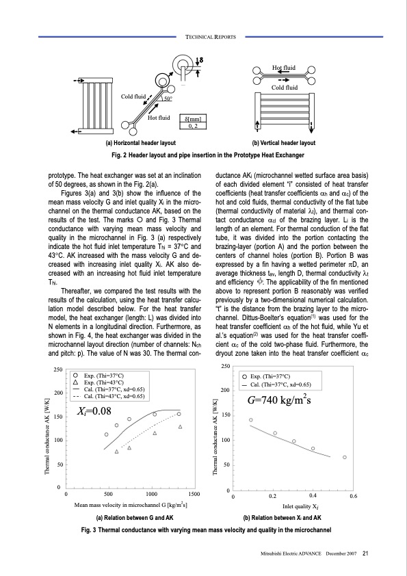
TECHNICAL REPORTS Cold fluid Hot fluid 50° δ[mm] δ Hot fluid Cold fluid (a) Horizontal header layout Fig. 2 Header layout and pipe insertion in the Prototype Heat Exchanger 0, 2 (b) Vertical header layout prototype. The heat exchanger was set at an inclination of 50 degrees, as shown in the Fig. 2(a). Figures 3(a) and 3(b) show the influence of the mean mass velocity G and inlet quality Xi in the micro- channel on the thermal conductance AK, based on the results of the test. The marks � and Fig. 3 Thermal conductance with varying mean mass velocity and quality in the microchannel in Fig. 3 (a) respectively indicate the hot fluid inlet temperature Thi = 37°C and 43°C. AK increased with the mass velocity G and de- creased with increasing inlet quality Xi. AK also de- creased with an increasing hot fluid inlet temperature Thi. Thereafter, we compared the test results with the results of the calculation, using the heat transfer calcu- lation model described below. For the heat transfer model, the heat exchanger (length: L) was divided into N elements in a longitudinal direction. Furthermore, as shown in Fig. 4, the heat exchanger was divided in the microchannel layout direction (number of channels: Nch and pitch: p). The value of N was 30. The thermal con- ductance AKi (microchannel wetted surface area basis) of each divided element “i” consisted of heat transfer coefficients (heat transfer coefficients αh and αc) of the hot and cold fluids, thermal conductivity of the flat tube (thermal conductivity of material λt), and thermal con- tact conductance αcl of the brazing layer. Li is the length of an element. For thermal conduction of the flat tube, it was divided into the portion contacting the brazing-layer (portion A) and the portion between the centers of channel holes (portion B). Portion B was expressed by a fin having a wetted perimeter πD, an average thickness tav, length D, thermal conductivity λt and efficiency . The applicability of the fin mentioned above to represent portion B reasonably was verified previously by a two-dimensional numerical calculation. “t” is the distance from the brazing layer to the micro- channel. Dittus-Boelter’s equation(1) was used for the heat transfer coefficient αh of the hot fluid, while Yu et al.’s equation(2) was used for the heat transfer coeffi- cient αc of the cold two-phase fluid. Furthermore, the dryout zone taken into the heat transfer coefficient αc Exp. (Thi=37°C) Cal. (Thi=37°C, xd=0.65) G=740 kg/m2s 250 200 150 100 50 0 0 250 200 150 100 50 0 Exp. (Thi=37°C) Exp. (Thi=43°C) Cal. (Thi=37°C, xd=0.65) Cal. (Thi=43°C, xd=0.65) Xi=0.08 500 Mean mass velocity in microchannel G [kg/m2s] 1500 1000 0 0.2 0.4 0.6 Inlet quality Xi (a) Relation between G and AK Fig. 3 Thermal conductance with varying mean mass velocity and quality in the microchannel (b) Relation between Xi and AK Mitsubishi Electric ADVANCE December 2007 21 Thermal conductance AK [W/K] Thermal conductance AK [W/K]PDF Image | Heat Pump with Natural Refrigerants 3041
PDF Search Title:
Heat Pump with Natural Refrigerants 3041Original File Name Searched:
vol120.pdfDIY PDF Search: Google It | Yahoo | Bing
CO2 Organic Rankine Cycle Experimenter Platform The supercritical CO2 phase change system is both a heat pump and organic rankine cycle which can be used for those purposes and as a supercritical extractor for advanced subcritical and supercritical extraction technology. Uses include producing nanoparticles, precious metal CO2 extraction, lithium battery recycling, and other applications... More Info
Heat Pumps CO2 ORC Heat Pump System Platform More Info
| CONTACT TEL: 608-238-6001 Email: greg@infinityturbine.com | RSS | AMP |