PDF Publication Title:
Text from PDF Page: 005
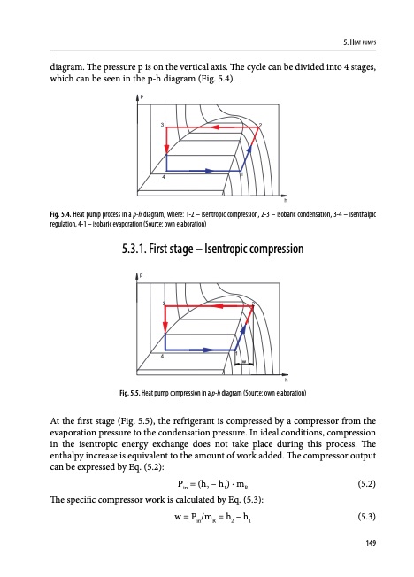
diagram. The pressure p is on the vertical axis. The cycle can be divided into 4 stages, which can be seen in the p-h diagram (Fig. 5.4). p 5. Heat pumps 32 4 1 h Fig. 5.4. Heat pump process in a p-h diagram, where: 1-2 – isentropic compression, 2-3 – isobaric condensation, 3-4 – isenthalpic regulation, 4-1 – isobaric evaporation (Source: own elaboration) 5.3.1. First stage – Isentropic compression p 4 1 w 32 h Fig. 5.5. Heat pump compression in a p-h diagram (Source: own elaboration) At the first stage (Fig. 5.5), the refrigerant is compressed by a compressor from the evaporation pressure to the condensation pressure. In ideal conditions, compression in the isentropic energy exchange does not take place during this process. The enthalpy increase is equivalent to the amount of work added. The compressor output can be expressed by Eq. (5.2): Pin = (h2 – h1) · mR (5.2) The specific compressor work is calculated by Eq. (5.3): w = Pin/mR = h2 – h1 (5.3) 149PDF Image | Heat Pumps 978-83-65596-73-4
PDF Search Title:
Heat Pumps 978-83-65596-73-4Original File Name Searched:
Buildings-2020-part2-rozdz5.pdfDIY PDF Search: Google It | Yahoo | Bing
CO2 Organic Rankine Cycle Experimenter Platform The supercritical CO2 phase change system is both a heat pump and organic rankine cycle which can be used for those purposes and as a supercritical extractor for advanced subcritical and supercritical extraction technology. Uses include producing nanoparticles, precious metal CO2 extraction, lithium battery recycling, and other applications... More Info
Heat Pumps CO2 ORC Heat Pump System Platform More Info
| CONTACT TEL: 608-238-6001 Email: greg@infinityturbine.com | RSS | AMP |