PDF Publication Title:
Text from PDF Page: 009
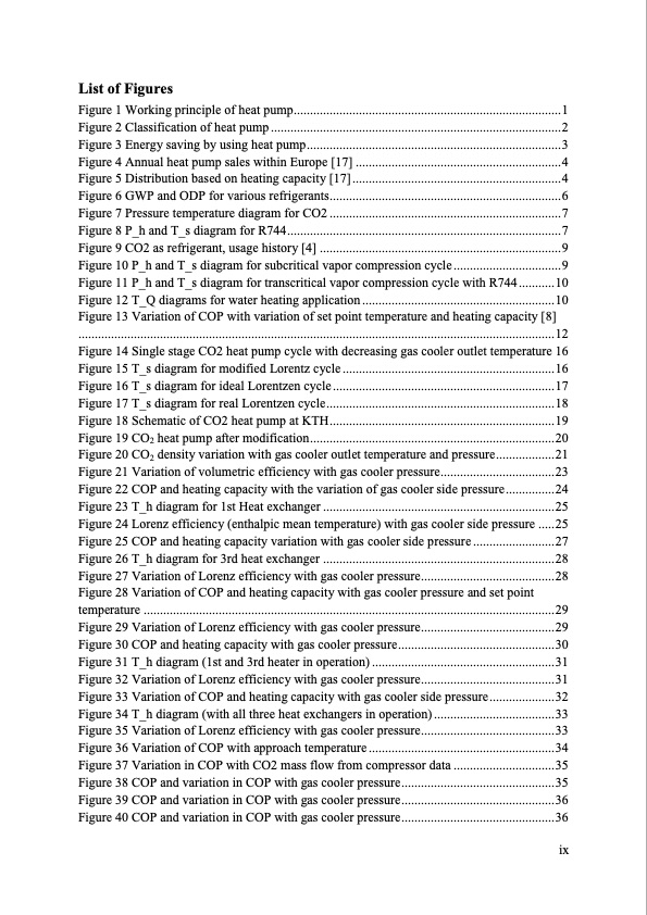
List of Figures Figure 1 Working principle of heat pump..................................................................................1 Figure 2 Classification of heat pump.........................................................................................2 Figure 3 Energy saving by using heat pump..............................................................................3 Figure 4 Annual heat pump sales within Europe [17] ...............................................................4 Figure 5 Distribution based on heating capacity [17]................................................................4 Figure 6 GWP and ODP for various refrigerants.......................................................................6 Figure 7 Pressure temperature diagram for CO2 .......................................................................7 Figure 8 P_h and T_s diagram for R744....................................................................................7 Figure 9 CO2 as refrigerant, usage history [4] ..........................................................................9 Figure 10 P_h and T_s diagram for subcritical vapor compression cycle.................................9 Figure 11 P_h and T_s diagram for transcritical vapor compression cycle with R744...........10 Figure 12 T_Q diagrams for water heating application...........................................................10 Figure 13 Variation of COP with variation of set point temperature and heating capacity [8] .................................................................................................................................................. 12 Figure 14 Single stage CO2 heat pump cycle with decreasing gas cooler outlet temperature 16 Figure 15 T_s diagram for modified Lorentz cycle.................................................................16 Figure 16 T_s diagram for ideal Lorentzen cycle....................................................................17 Figure 17 T_s diagram for real Lorentzen cycle......................................................................18 Figure 18 Schematic of CO2 heat pump at KTH.....................................................................19 Figure 19 CO2 heat pump after modification...........................................................................20 Figure 20 CO2 density variation with gas cooler outlet temperature and pressure..................21 Figure 21 Variation of volumetric efficiency with gas cooler pressure...................................23 Figure 22 COP and heating capacity with the variation of gas cooler side pressure...............24 Figure 23 T_h diagram for 1st Heat exchanger .......................................................................25 Figure 24 Lorenz efficiency (enthalpic mean temperature) with gas cooler side pressure .....25 Figure 25 COP and heating capacity variation with gas cooler side pressure.........................27 Figure 26 T_h diagram for 3rd heat exchanger .......................................................................28 Figure 27 Variation of Lorenz efficiency with gas cooler pressure.........................................28 Figure 28 Variation of COP and heating capacity with gas cooler pressure and set point temperature ..............................................................................................................................29 Figure 29 Variation of Lorenz efficiency with gas cooler pressure.........................................29 Figure 30 COP and heating capacity with gas cooler pressure................................................30 Figure 31 T_h diagram (1st and 3rd heater in operation) ........................................................ 31 Figure 32 Variation of Lorenz efficiency with gas cooler pressure.........................................31 Figure 33 Variation of COP and heating capacity with gas cooler side pressure....................32 Figure 34 T_h diagram (with all three heat exchangers in operation).....................................33 Figure 35 Variation of Lorenz efficiency with gas cooler pressure.........................................33 Figure 36 Variation of COP with approach temperature.........................................................34 Figure 37 Variation in COP with CO2 mass flow from compressor data ...............................35 Figure 38 COP and variation in COP with gas cooler pressure...............................................35 Figure 39 COP and variation in COP with gas cooler pressure...............................................36 Figure 40 COP and variation in COP with gas cooler pressure...............................................36 ixPDF Image | heat recovery from R744 based refrigeration system

PDF Search Title:
heat recovery from R744 based refrigeration systemOriginal File Name Searched:
r744-heat-recovery.pdfDIY PDF Search: Google It | Yahoo | Bing
CO2 Organic Rankine Cycle Experimenter Platform The supercritical CO2 phase change system is both a heat pump and organic rankine cycle which can be used for those purposes and as a supercritical extractor for advanced subcritical and supercritical extraction technology. Uses include producing nanoparticles, precious metal CO2 extraction, lithium battery recycling, and other applications... More Info
Heat Pumps CO2 ORC Heat Pump System Platform More Info
| CONTACT TEL: 608-238-6001 Email: greg@infinityturbine.com | RSS | AMP |