PDF Publication Title:
Text from PDF Page: 003
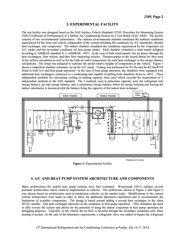
2. EXPERIMENTAL FACILITY The test facility was designed based on the SAE Surface Vehicle Standard, J2765; Procedure for Measuring System COP [Coefficient of Performance] of a Mobile Air Conditioning System on a Test Bench (SAE, 2008). The facility consists of two environmental calorimeters. The outdoor environmental chamber simulated the ambient conditions experienced by the front end vehicle components of the system including the condenser (in A/C operation), internal heat exchanger, and compressor. The indoor chamber simulated the conditions experienced by the evaporator (in A/C mode) and the secondary condenser (in heat pump mode). Each chamber contained a wind tunnel designed according to ASHRAE standard 41.2 (ASHRAE, 1987). In the case of both wind tunnels, the air passes through the heat exchangers, flow mixers, and then flow measuring nozzles. Thermocouples in the nozzle throat are then used in the airflow calculation as well as for the bulk air outlet temperature for each heat exchanger in the energy balance calculations. The setup was designed to replicate the actual relative heights of components in the vehicle. Figure 1 shows a simplified chamber schematic set up for A/C mode. Testing was performed for R134a and the R134a/R744 blend in both A/C and heat pump operation. In the case of heat pump operation, the chambers were equipped with additional heat exchangers connected to a condensing unit capable of pulling both chambers down to -40°C. Three independent methods for calculating cooling or heating capacity were used which exceeds the requirement of 2 independent methods in the SAE standard. The 3 methods used to determine capacity were the refrigerant side energy balance, air side energy balance, and a calorimeter energy balance where all energy entering and leaving the indoor calorimeter is measured with the balance being the capacity of the indoor heat exchanger. 2509, Page 2 Tgo Tgi Glycol Chiller Indoor Chamber Outdoor Chamber 7" 7" P, T_xri Mr XV P, T_cro P, T_cri DPca P, T_ero Comp Vcp, Acp Tdpei Dew Point Sensor Dew Point Sensor DPea DPen DPcn Figure 1: Experimental Facility 3. A/C AND HEAT PUMP SYSTEM ARCHITECTURE AND COMPONENTS Many architectures for mobile heat pump systems were first evaluated. Wawzyniak (2011) outlines several potential architectures which could be implemented in vehicles. The architecture shown in Figure 2 and Figure 3 was chosen based on architectures used in production vehicles on the market today. Modifications to the current vehicle architectures were made in order to allow for additional laboratory exploration and to accommodate the limitations of available components. The design is based around adding a second heat exchanger in the cabin HVAC module. This heat exchanger functions as the condenser in heat pump operation. This eliminates the need to fully reverse the system and allows for the potential of using the indoor evaporator in heat pump operation for defogging purposes. Typically, in the vehicle the air flow is diverted through the secondary condenser only when heating is needed. In the case of the laboratory experiments, a refrigerant valve was added to bypass the refrigerant 15th International Refrigeration and Air Conditioning Conference at Purdue, July 14-17, 2014 * Drawing not to scale Air out Air out Blower Humidifier Electric Heater Electric Heater Chiller Blower Diffusion Baffle NOZZLE 3" Ten Diffusion Baffle Air mixer Teao grid Indoor HX Tcao grid Air mixer Diffusion Baffle NOZZLE Tcn Diffusion Baffle Teai Tdpen P, T_cpri P, T_cpro Tcai Outdoor HX P, T _eriPDF Image | Mobile Heat Pump Exploration Using R445A and R744
PDF Search Title:
Mobile Heat Pump Exploration Using R445A and R744Original File Name Searched:
mobile-heat-pump-r744.pdfDIY PDF Search: Google It | Yahoo | Bing
CO2 Organic Rankine Cycle Experimenter Platform The supercritical CO2 phase change system is both a heat pump and organic rankine cycle which can be used for those purposes and as a supercritical extractor for advanced subcritical and supercritical extraction technology. Uses include producing nanoparticles, precious metal CO2 extraction, lithium battery recycling, and other applications... More Info
Heat Pumps CO2 ORC Heat Pump System Platform More Info
| CONTACT TEL: 608-238-6001 Email: greg@infinityturbine.com | RSS | AMP |