PDF Publication Title:
Text from PDF Page: 034
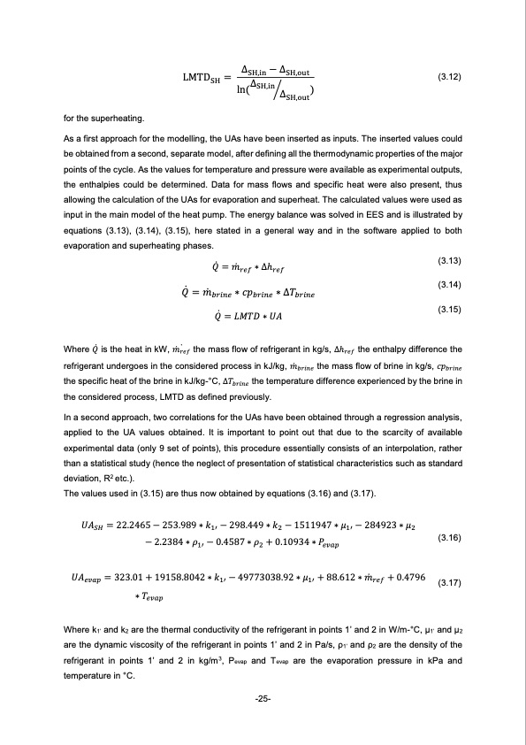
LMTDSH = ΔSH,in − ΔSH,out ΔSH,in ln( ⁄ ) ΔSH,out (3.12) for the superheating. As a first approach for the modelling, the UAs have been inserted as inputs. The inserted values could be obtained from a second, separate model, after defining all the thermodynamic properties of the major points of the cycle. As the values for temperature and pressure were available as experimental outputs, the enthalpies could be determined. Data for mass flows and specific heat were also present, thus allowing the calculation of the UAs for evaporation and superheat. The calculated values were used as input in the main model of the heat pump. The energy balance was solved in EES and is illustrated by equations (3.13), (3.14), (3.15), here stated in a general way and in the software applied to both evaporation and superheating phases. Where 𝑄̇ is the heat in kW, 𝑚̇ 𝑟̇𝑒𝑓 the mass flow of refrigerant in kg/s, ∆h𝑟𝑒𝑓 the enthalpy difference the refrigerant undergoes in the considered process in kJ/kg, 𝑚̇ 𝑏𝑟𝑖𝑛𝑒 the mass flow of brine in kg/s, 𝑐𝑝𝑏𝑟𝑖𝑛𝑒 the specific heat of the brine in kJ/kg-°C, ∆𝑇𝑏𝑟𝑖𝑛𝑒 the temperature difference experienced by the brine in the considered process, LMTD as defined previously. In a second approach, two correlations for the UAs have been obtained through a regression analysis, applied to the UA values obtained. It is important to point out that due to the scarcity of available experimental data (only 9 set of points), this procedure essentially consists of an interpolation, rather than a statistical study (hence the neglect of presentation of statistical characteristics such as standard deviation, R2 etc.). The values used in (3.15) are thus now obtained by equations (3.16) and (3.17). ̇ 𝑄 = 𝑚̇ 𝑟 𝑒 𝑓 ∗ ∆ h 𝑟 𝑒 𝑓 ̇ 𝑄 = 𝑚̇ ∗ 𝑐𝑝 ∗ ∆𝑇 𝑏𝑟𝑖𝑛𝑒 𝑏𝑟𝑖𝑛𝑒 𝑏𝑟𝑖𝑛𝑒 ̇ 𝑄 = 𝐿𝑀𝑇𝐷 ∗ 𝑈𝐴 (3.13) (3.14) (3.15) 𝑈𝐴𝑆𝐻 = 22.2465 − 253.989 ∗ 𝑘1′ − 298.449 ∗ 𝑘2 − 1511947 ∗ 𝜇1′ − 284923 ∗ 𝜇2 −2.2384∗𝜌 −0.4587∗𝜌 +0.10934∗𝑃 1′ 2 𝑒𝑣𝑎𝑝 (3.16) 𝑈𝐴𝑒𝑣𝑎𝑝 = 323.01 + 19158.8042 ∗ 𝑘1′ − 49773038.92 ∗ 𝜇1′ + 88.612 ∗ 𝑚̇ 𝑟𝑒𝑓 + 0.4796 ∗𝑇 𝑒𝑣𝑎𝑝 (3.17) Where k1’ and k2 are the thermal conductivity of the refrigerant in points 1’ and 2 in W/m-°C, μ1’ and μ2 are the dynamic viscosity of the refrigerant in points 1’ and 2 in Pa/s, ρ1’ and ρ2 are the density of the refrigerant in points 1’ and 2 in kg/m3, Pevap and Tevap are the evaporation pressure in kPa and temperature in °C. -25-PDF Image | Next generation of refrigerants for residential heat pump systems

PDF Search Title:
Next generation of refrigerants for residential heat pump systemsOriginal File Name Searched:
MartinaLonghini_ThesisReport.pdfDIY PDF Search: Google It | Yahoo | Bing
CO2 Organic Rankine Cycle Experimenter Platform The supercritical CO2 phase change system is both a heat pump and organic rankine cycle which can be used for those purposes and as a supercritical extractor for advanced subcritical and supercritical extraction technology. Uses include producing nanoparticles, precious metal CO2 extraction, lithium battery recycling, and other applications... More Info
Heat Pumps CO2 ORC Heat Pump System Platform More Info
| CONTACT TEL: 608-238-6001 Email: greg@infinityturbine.com | RSS | AMP |