PDF Publication Title:
Text from PDF Page: 003
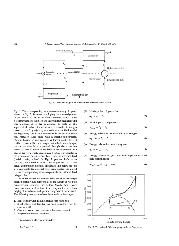
832 J. Sarkar et al. / International Journal of Refrigeration 27 (2004) 830–838 Fig. 1. The corresponding temperature – entropy diagram, shown in Fig. 2, is drawn employing the thermodynamic property code CO2PROP. As shown, saturated vapor at state 6 is superheated to state 1 in the internal heat exchanger and then compressed in the compressor to state 2. The supercritical carbon dioxide at state 2 is cooled in the gas cooler to state 3 by rejecting heat to the external fluid (useful heating effect). Unlike in a condenser, in the gas cooler the heat rejection takes place with a gliding temperature. Carbon dioxide at high pressure is further cooled from 3 to 4 in the internal heat exchanger. After the heat exchanger, the carbon dioxide is expanded through the expansion device to state 5, which is the inlet to the evaporator. The state of the refrigerant changes from 5 to 6 as it evaporates in the evaporator by extracting heat from the external fluid (useful cooling effect). In Fig. 2, process 1–2s is an isentropic compression process, while process 1–2 is the actual compression process. The dotted line below process 2–3 represents the external fluid being heated and dotted line above evaporating process represents the external fluid being cooled. The entire system has been modeled based on the energy balance of individual components of the system to yield the conservations equations that follow. Steady flow energy equations based on first law of thermodynamics have been employed in each case and specific energy quantities are used. The following assumptions have been made in the analysis: 1. Heattransferwiththeambienthasbeenneglected. 2. Single-phase heat transfer has been considered for the external fluid. 3. Compressionprocessisadiabaticbutnon-isentropic. 4. Evaporationprocessisisobaric. (i) Refrigerating effect of evaporator: qev1⁄4h62h5 ð1Þ (ii) Heating effect of gas cooler: qgc 1⁄4 h2 2 h3 ð2Þ (iii) Work input to compressor: wcomp 1⁄4 h2 2 h1 ð3Þ (iv) Energy balance in the internal heat exchanger: h1 2 h6 1⁄4 h3 2 h4 ð4Þ (v) Energy balance for the entire system: qev þ wcomp 1⁄4 qgc ð5Þ (vi) Energy balance for gas cooler with respect to external fluid being heated: m_gcefcp;gcefDTgcef 1⁄4m_rqgc ð6Þ Fig. 2. Transcritical CO2 heat pump cycle on T – s plane. Fig. 1. Schematic diagram of a transcritical carbon dioxide system.PDF Image | Optimization of a transcritical CO2 heat pump cycle
PDF Search Title:
Optimization of a transcritical CO2 heat pump cycleOriginal File Name Searched:
transcritical-co2-heat-pump.pdfDIY PDF Search: Google It | Yahoo | Bing
CO2 Organic Rankine Cycle Experimenter Platform The supercritical CO2 phase change system is both a heat pump and organic rankine cycle which can be used for those purposes and as a supercritical extractor for advanced subcritical and supercritical extraction technology. Uses include producing nanoparticles, precious metal CO2 extraction, lithium battery recycling, and other applications... More Info
Heat Pumps CO2 ORC Heat Pump System Platform More Info
| CONTACT TEL: 608-238-6001 Email: greg@infinityturbine.com | RSS | AMP |