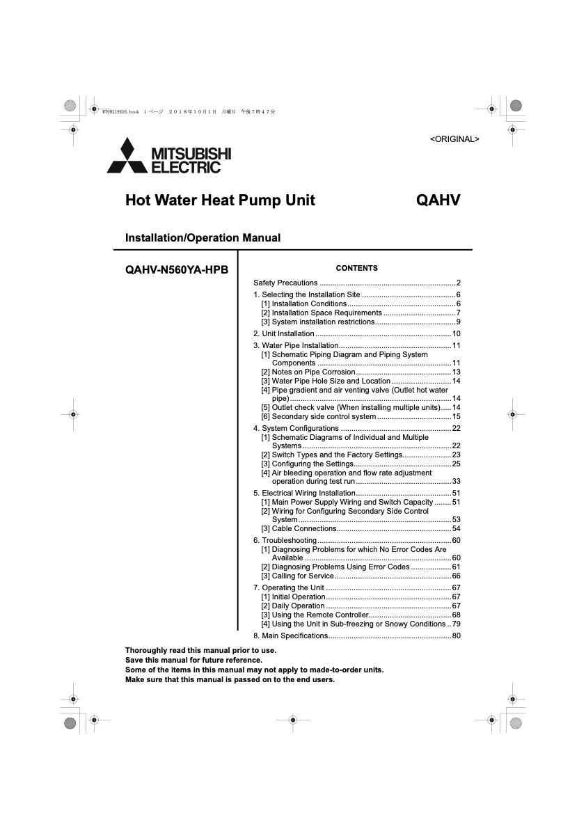
Safety Precautions ................................................................2
1. Selecting the Installation Site ............................................6 [1] Installation Conditions...................................................6 [2] Installation Space Requirements .................................. 7 [3] System installation restrictions......................................9
2. Unit Installation................................................................10
3. Water Pipe Installation.....................................................11
[1] Schematic Piping Diagram and Piping System
Components ...............................................................11
[2] Notes on Pipe Corrosion.............................................13
[3] Water Pipe Hole Size and Location ............................ 14
[4] Pipe gradient and air venting valve (Outlet hot water
pipe) ............................................................................ 14
[5] Outlet check valve (When installing multiple units).....14
[6] Secondary side control system...................................15
4. System Configurations ....................................................22
[1] Schematic Diagrams of Individual and Multiple
Systems ...................................................................... 22
[2] Switch Types and the Factory Settings.......................23
[3] Configuring the Settings..............................................25
[4] Air bleeding operation and flow rate adjustment
operation during test run.............................................33
5. Electrical Wiring Installation.............................................51
[1] Main Power Supply Wiring and Switch Capacity ........ 51
[2] Wiring for Configuring Secondary Side Control
System ........................................................................ 53
[3] Cable Connections......................................................54
6. Troubleshooting...............................................................60
[1] Diagnosing Problems for which No Error Codes Are
Available ..................................................................... 60
[2] Diagnosing Problems Using Error Codes ................... 61
[3] Calling for Service.......................................................66
7. Operating the Unit ...........................................................67 [1] Initial Operation...........................................................67 [2] Daily Operation ........................................................... 67 [3] Using the Remote Controller.......................................68 [4] Using the Unit in Sub-freezing or Snowy Conditions .. 79
8. Main Specifications..........................................................80
Thoroughly read this manual prior to use.
Save this manual for future reference.
Some of the items in this manual may not apply to made-to-order units. Make sure that this manual is passed on to the end users.
CONTENTS
PDF Image | QAHV-N560YA-HPB

PDF Search Title:
QAHV-N560YA-HPB
Original File Name Searched:
IBIM_WT08219X05_QAHV_N560YA_HPB_ML.pdf
DIY PDF Search: Google It | Yahoo | Bing
CO2 Organic Rankine Cycle Experimenter Platform The supercritical CO2 phase change system is both a heat pump and organic rankine cycle which can be used for those purposes and as a supercritical extractor for advanced subcritical and supercritical extraction technology. Uses include producing nanoparticles, precious metal CO2 extraction, lithium battery recycling, and other applications... More Info
Heat Pumps CO2 ORC Heat Pump System Platform More Info

