PDF Publication Title:
Text from PDF Page: 019
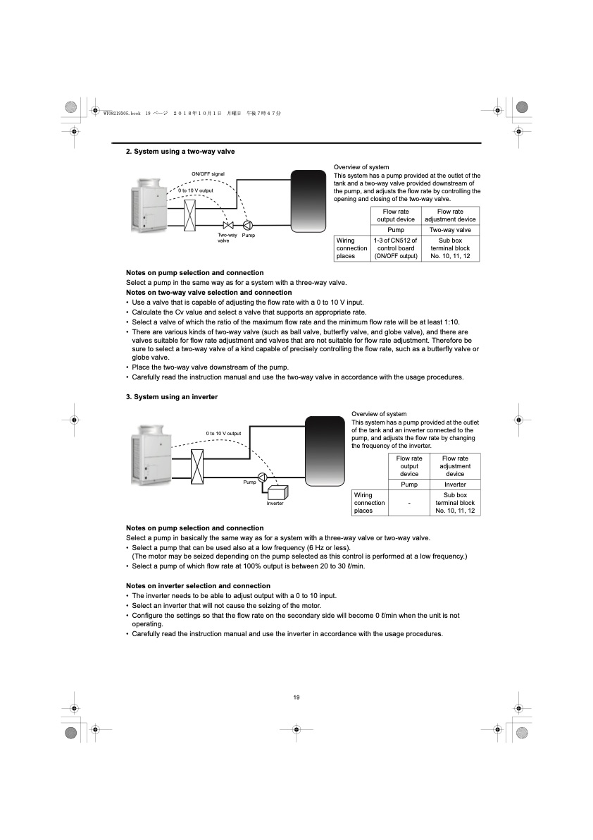
2. System using a two-way valve ON/OFF signal 0 to 10 V output Two-way Pump valve Notes on pump selection and connection Overview of system This system has a pump provided at the outlet of the tank and a two-way valve provided downstream of the pump, and adjusts the flow rate by controlling the opening and closing of the two-way valve. Wiring connection places 1-3 of CN512 of control board (ON/OFF output) Select a pump in the same way as for a system with a three-way valve. Notes on two-way valve selection and connection • Use a valve that is capable of adjusting the flow rate with a 0 to 10 V input. • Calculate the Cv value and select a valve that supports an appropriate rate. • Select a valve of which the ratio of the maximum flow rate and the minimum flow rate will be at least 1:10. • There are various kinds of two-way valve (such as ball valve, butterfly valve, and globe valve), and there are valves suitable for flow rate adjustment and valves that are not suitable for flow rate adjustment. Therefore be sure to select a two-way valve of a kind capable of precisely controlling the flow rate, such as a butterfly valve or globe valve. • Place the two-way valve downstream of the pump. • Carefully read the instruction manual and use the two-way valve in accordance with the usage procedures. 3. System using an inverter Notes on pump selection and connection Overview of system This system has a pump provided at the outlet of the tank and an inverter connected to the pump, and adjusts the flow rate by changing the frequency of the inverter. Wiring connection places 0 to 10 V output Pump Inverter Flow rate output device Pump - Two-way valve Sub box terminal block No. 10, 11, 12 Flow rate adjustment device Inverter Sub box terminal block No. 10, 11, 12 Select a pump in basically the same way as for a system with a three-way valve or two-way valve. • Select a pump that can be used also at a low frequency (6 Hz or less). (The motor may be seized depending on the pump selected as this control is performed at a low frequency.) • Select a pump of which flow rate at 100% output is between 20 to 30 l/min. Notes on inverter selection and connection • The inverter needs to be able to adjust output with a 0 to 10 input. • Select an inverter that will not cause the seizing of the motor. • Configure the settings so that the flow rate on the secondary side will become 0 l/min when the unit is not operating. • Carefully read the instruction manual and use the inverter in accordance with the usage procedures. 19 Flow rate output device Pump Flow rate adjustment devicePDF Image | QAHV-N560YA-HPB
PDF Search Title:
QAHV-N560YA-HPBOriginal File Name Searched:
IBIM_WT08219X05_QAHV_N560YA_HPB_ML.pdfDIY PDF Search: Google It | Yahoo | Bing
CO2 Organic Rankine Cycle Experimenter Platform The supercritical CO2 phase change system is both a heat pump and organic rankine cycle which can be used for those purposes and as a supercritical extractor for advanced subcritical and supercritical extraction technology. Uses include producing nanoparticles, precious metal CO2 extraction, lithium battery recycling, and other applications... More Info
Heat Pumps CO2 ORC Heat Pump System Platform More Info
| CONTACT TEL: 608-238-6001 Email: greg@infinityturbine.com | RSS | AMP |