PDF Publication Title:
Text from PDF Page: 028
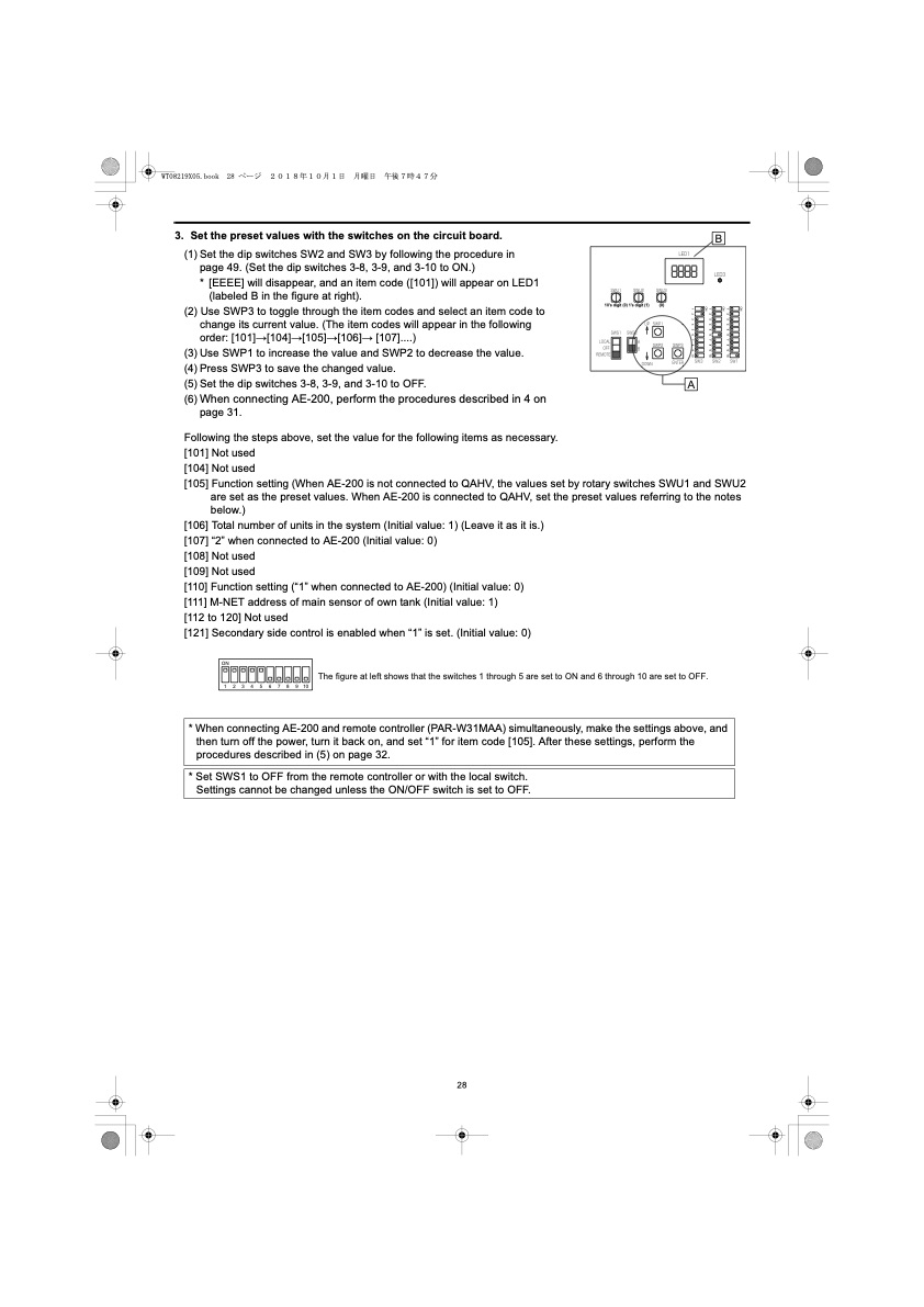
3. Set the preset values with the switches on the circuit board. (1) Set the dip switches SW2 and SW3 by following the procedure in page 49. (Set the dip switches 3-8, 3-9, and 3-10 to ON.) * [EEEE] will disappear, and an item code ([101]) will appear on LED1 (labeled B in the figure at right). (2) Use SWP3 to toggle through the item codes and select an item code to change its current value. (The item codes will appear in the following order: [101]→[104]→[105]→[106]→ [107]....) (3) Use SWP1 to increase the value and SWP2 to decrease the value. (4) Press SWP3 to save the changed value. (5) Set the dip switches 3-8, 3-9, and 3-10 to OFF. (6) When connecting AE-200, perform the procedures described in 4 on page 31. Following the steps above, set the value for the following items as necessary. [101] Not used [104] Not used [105] Function setting (When AE-200 is not connected to QAHV, the values set by rotary switches SWU1 and SWU2 are set as the preset values. When AE-200 is connected to QAHV, set the preset values referring to the notes below.) [106] Total number of units in the system (Initial value: 1) (Leave it as it is.) [107] “2” when connected to AE-200 (Initial value: 0) [108] Not used [109] Not used [110] Function setting (“1” when connected to AE-200) (Initial value: 0) [111] M-NET address of main sensor of own tank (Initial value: 1) [112 to 120] Not used [121] Secondary side control is enabled when “1” is set. (Initial value: 0) * Set SWS1 to OFF from the remote controller or with the local switch. Settings cannot be changed unless the ON/OFF switch is set to OFF. 10’s digit (0) 1’s digit (1) (0) A B ON 1 2 3 4 5 6 7 8 9 10 The figure at left shows that the switches 1 through 5 are set to ON and 6 through 10 are set to OFF. * When connecting AE-200 and remote controller (PAR-W31MAA) simultaneously, make the settings above, and then turn off the power, turn it back on, and set “1” for item code [105]. After these settings, perform the procedures described in (5) on page 32. 28 ON 1 2 3 4 5 6 7 8 9 10 ON 1 2 3 4 5 6 7 8 9 10 ON 1 2 3 4 5 6 7 8 9 10PDF Image | QAHV-N560YA-HPB
PDF Search Title:
QAHV-N560YA-HPBOriginal File Name Searched:
IBIM_WT08219X05_QAHV_N560YA_HPB_ML.pdfDIY PDF Search: Google It | Yahoo | Bing
CO2 Organic Rankine Cycle Experimenter Platform The supercritical CO2 phase change system is both a heat pump and organic rankine cycle which can be used for those purposes and as a supercritical extractor for advanced subcritical and supercritical extraction technology. Uses include producing nanoparticles, precious metal CO2 extraction, lithium battery recycling, and other applications... More Info
Heat Pumps CO2 ORC Heat Pump System Platform More Info
| CONTACT TEL: 608-238-6001 Email: greg@infinityturbine.com | RSS | AMP |