PDF Publication Title:
Text from PDF Page: 031
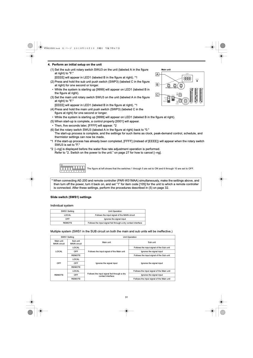
4. Perform an initial setup on the unit (1) Set the sub unit rotary switch SWU3 on the unit (labeled A in the figure at right) to "F." [EEEE] will appear in LED1 (labeled B in the figure at right). *1 (2) Press and hold the sub unit push switch (SWP3) (labeled C in the figure at right) for one second or longer. • While the system is starting up [9999] will appear on LED1 (labeled B in the figure at right). (3) Set the main unit rotary switch SWU3 on the unit (labeled A in the figure at right) to "F." [EEEE] will appear in LED1 (labeled B in the figure at right). *1 (4) Press and hold the main unit push switch (SWP3) (labeled C in the figure at right) for one second or longer. • While the system is starting up [9999] will appear on LED1 (labeled B in the figure at right). (5) When start-up is complete, a control property [0001] will appear. • Then, five seconds later, [FFFF] will appear. *2 (6) Set the rotary switch SWU3 (labeled A in the figure at right) back to "0." The start-up process is complete, and the settings for such items as clock, peak-demand control, schedule, and thermistor settings can now be made. *1 If the start-up process has already been completed, [FFFF] (instead of [EEEE]) will appear when the rotary switch SWU3 is set to "F." *2 [--ng] is displayed before the water flow rate adjustment operation is performed. Refer to “2. Switch on the power to the unit.” on page 27 for how to cancel [--ng]. A B C Main unit 10’s digit (0) 1’s digit (1) (0) ON 1 2 3 4 5 6 7 8 9 10 The figure at left shows that the switches 1 through 5 are set to ON and 6 through 10 are set to OFF. * When connecting AE-200 and remote controller (PAR-W31MAA) simultaneously, make the settings above, and then turn off the power, turn it back on, and set “1” for item code [105] for the unit to which a remote controller is connected. After these settings, perform the procedures described in (5) on page 32. Slide switch (SWS1) settings Individual system Multiple system (SWS1 in the SUB circuit on both the main and sub units will be ineffective.) SWS1 Setting Unit Operation LOCAL Follows the input signal of the MAIN circuit OFF Ignores the signal input REMOTE Follows the input signal fed through a dry contact interface SWS1 Setting Unit Operation Main unit MAIN circuit Sub unit MAIN circuit Main unit Sub unit LOCAL LOCAL Follows the input signal of the Main unit Follows the input signal of the Sub unit OFF Ignores the signal input REMOTE Follows the input signal of the Sub unit OFF LOCAL Ignores the signal input Ignores the signal input OFF REMOTE REMOTE LOCAL Follows the input signal fed through a dry contact interface Follows the input signal of the Main unit OFF Ignores the signal input REMOTE Follows the input signal of the Main unit 31 ON 1 2 3 4 5 6 7 8 9 10 ON 1 2 3 4 5 6 7 8 9 10 ON 1 2 3 4 5 6 7 8 9 10PDF Image | QAHV-N560YA-HPB
PDF Search Title:
QAHV-N560YA-HPBOriginal File Name Searched:
IBIM_WT08219X05_QAHV_N560YA_HPB_ML.pdfDIY PDF Search: Google It | Yahoo | Bing
CO2 Organic Rankine Cycle Experimenter Platform The supercritical CO2 phase change system is both a heat pump and organic rankine cycle which can be used for those purposes and as a supercritical extractor for advanced subcritical and supercritical extraction technology. Uses include producing nanoparticles, precious metal CO2 extraction, lithium battery recycling, and other applications... More Info
Heat Pumps CO2 ORC Heat Pump System Platform More Info
| CONTACT TEL: 608-238-6001 Email: greg@infinityturbine.com | RSS | AMP |