PDF Publication Title:
Text from PDF Page: 033
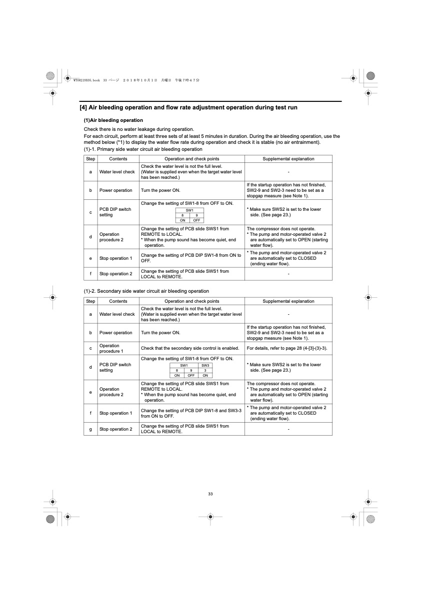
[4] Air bleeding operation and flow rate adjustment operation during test run (1)Air bleeding operation Check there is no water leakage during operation. For each circuit, perform at least three sets of at least 5 minutes in duration. During the air bleeding operation, use the method below (*1) to display the water flow rate during operation and check it is stable (no air entrainment). (1)-1. Primary side water circuit air bleeding operation Step Contents Operation and check points Supplemental explanation a Water level check Check the water level is not the full level. (Water is supplied even when the target water level has been reached.) - b Power operation Turn the power ON. If the startup operation has not finished, SW2-9 and SW2-3 need to be set as a stopgap measure (see Note 1). c PCB DIP switch setting Change the setting of SW1-8 from OFF to ON. SW1 89 ON OFF * Make sure SWS2 is set to the lower side. (See page 23.) d Operation procedure 2 Change the setting of PCB slide SWS1 from REMOTE to LOCAL. * When the pump sound has become quiet, end operation. The compressor does not operate. * The pump and motor-operated valve 2 are automatically set to OPEN (starting water flow). e Stop operation 1 Change the setting of PCB DIP SW1-8 from ON to OFF. * The pump and motor-operated valve 2 are automatically set to CLOSED (ending water flow). f Stop operation 2 Change the setting of PCB slide SWS1 from LOCAL to REMOTE. - (1)-2. Secondary side water circuit air bleeding operation Step Contents Operation and check points Supplemental explanation a Water level check Check the water level is not the full level. (Water is supplied even when the target water level has been reached.) - b Power operation Turn the power ON. If the startup operation has not finished, SW2-9 and SW2-3 need to be set as a stopgap measure (see Note 1). c Operation procedure 1 Check that the secondary side control is enabled. For details, refer to page 28 (4-[3]-(3)-3). d PCB DIP switch setting Change the setting of SW1-8 from OFF to ON. SW1 SW3 893 ON OFF ON * Make sure SWS2 is set to the lower side. (See page 23.) e Operation procedure 2 Change the setting of PCB slide SWS1 from REMOTE to LOCAL. * When the pump sound has become quiet, end operation. The compressor does not operate. * The pump and motor-operated valve 2 are automatically set to OPEN (starting water flow). f Stop operation 1 Change the setting of PCB DIP SW1-8 and SW3-3 from ON to OFF. * The pump and motor-operated valve 2 are automatically set to CLOSED (ending water flow). g Stop operation 2 Change the setting of PCB slide SWS1 from LOCAL to REMOTE. - 33PDF Image | QAHV-N560YA-HPB
PDF Search Title:
QAHV-N560YA-HPBOriginal File Name Searched:
IBIM_WT08219X05_QAHV_N560YA_HPB_ML.pdfDIY PDF Search: Google It | Yahoo | Bing
CO2 Organic Rankine Cycle Experimenter Platform The supercritical CO2 phase change system is both a heat pump and organic rankine cycle which can be used for those purposes and as a supercritical extractor for advanced subcritical and supercritical extraction technology. Uses include producing nanoparticles, precious metal CO2 extraction, lithium battery recycling, and other applications... More Info
Heat Pumps CO2 ORC Heat Pump System Platform More Info
| CONTACT TEL: 608-238-6001 Email: greg@infinityturbine.com | RSS | AMP |