PDF Publication Title:
Text from PDF Page: 051
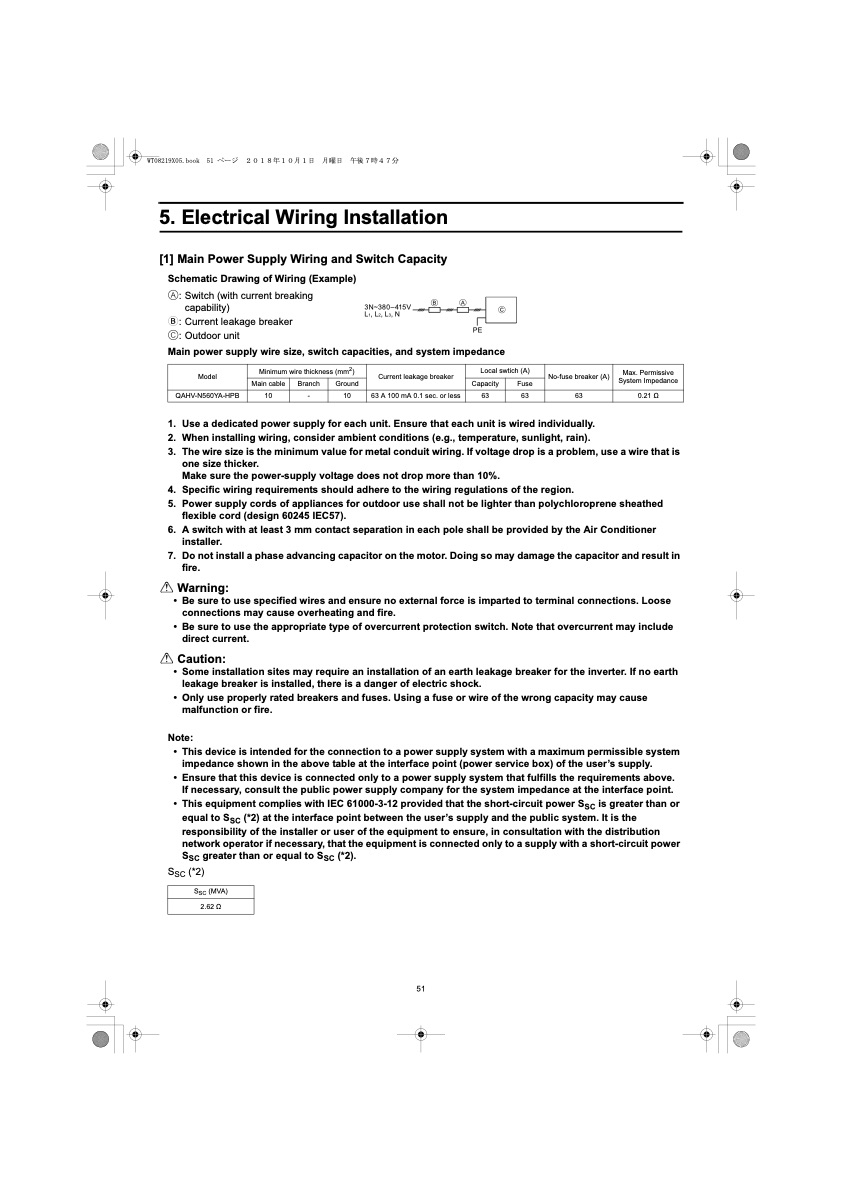
5. Electrical Wiring Installation [1] Main Power Supply Wiring and Switch Capacity Schematic Drawing of Wiring (Example) A: Switch (with current breaking capability) B: Current leakage breaker C: Outdoor unit Main power supply wire size, switch capacities, and system impedance 3N~380–415V L1, L2, L3, N BA PE Model Minimum wire thickness (mm2) Main cable Branch Ground QAHV-N560YA-HPB 10 - 10 Current leakage breaker 63 A 100 mA 0.1 sec. or less Local swtich (A) Capacity Fuse 63 63 No-fuse breaker (A) 63 Max. Permissive System Impedance 0.21 Ω 1. Use a dedicated power supply for each unit. Ensure that each unit is wired individually. 2. When installing wiring, consider ambient conditions (e.g., temperature, sunlight, rain). 3. Thewiresizeistheminimumvalueformetalconduitwiring.Ifvoltagedropisaproblem,useawirethatis one size thicker. Make sure the power-supply voltage does not drop more than 10%. 4. Specific wiring requirements should adhere to the wiring regulations of the region. 5. Power supply cords of appliances for outdoor use shall not be lighter than polychloroprene sheathed flexible cord (design 60245 IEC57). 6. A switch with at least 3 mm contact separation in each pole shall be provided by the Air Conditioner installer. 7. Donotinstallaphaseadvancingcapacitoronthemotor.Doingsomaydamagethecapacitorandresultin fire. Warning: • Be sure to use specified wires and ensure no external force is imparted to terminal connections. Loose connections may cause overheating and fire. • Be sure to use the appropriate type of overcurrent protection switch. Note that overcurrent may include direct current. Caution: • Some installation sites may require an installation of an earth leakage breaker for the inverter. If no earth leakage breaker is installed, there is a danger of electric shock. • Only use properly rated breakers and fuses. Using a fuse or wire of the wrong capacity may cause malfunction or fire. Note: • This device is intended for the connection to a power supply system with a maximum permissible system impedance shown in the above table at the interface point (power service box) of the user’s supply. • Ensure that this device is connected only to a power supply system that fulfills the requirements above. If necessary, consult the public power supply company for the system impedance at the interface point. • This equipment complies with IEC 61000-3-12 provided that the short-circuit power SSC is greater than or equal to SSC (*2) at the interface point between the user’s supply and the public system. It is the responsibility of the installer or user of the equipment to ensure, in consultation with the distribution network operator if necessary, that the equipment is connected only to a supply with a short-circuit power SSC greater than or equal to SSC (*2). SSC (*2) SSC (MVA) 2.62 Ω 51 CPDF Image | QAHV-N560YA-HPB
PDF Search Title:
QAHV-N560YA-HPBOriginal File Name Searched:
IBIM_WT08219X05_QAHV_N560YA_HPB_ML.pdfDIY PDF Search: Google It | Yahoo | Bing
CO2 Organic Rankine Cycle Experimenter Platform The supercritical CO2 phase change system is both a heat pump and organic rankine cycle which can be used for those purposes and as a supercritical extractor for advanced subcritical and supercritical extraction technology. Uses include producing nanoparticles, precious metal CO2 extraction, lithium battery recycling, and other applications... More Info
Heat Pumps CO2 ORC Heat Pump System Platform More Info
| CONTACT TEL: 608-238-6001 Email: greg@infinityturbine.com | RSS | AMP |