PDF Publication Title:
Text from PDF Page: 056
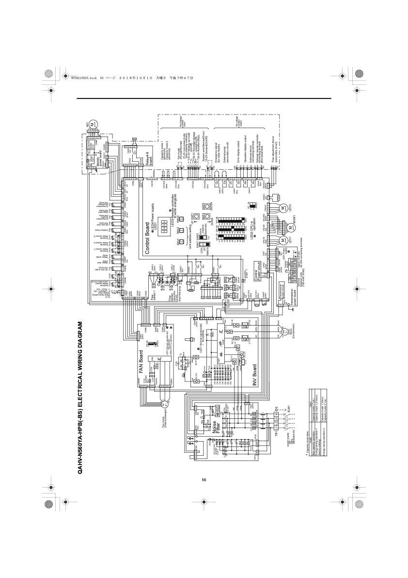
7654321 1234567 1234567 54321 4321 432 1 654321654321765432176543217654321321 12 12 123456789 2 1 7 6 5 4 3 2 1 3 2 1 123 654321 4321 21 56 123 Z21 t° 1231212312 12 1234 123456 CNDC pink 123 12345 612312 +12V 12123 +12V +12V GND 21 Gascooler Ref temp 10 9 8 7 6 5 4 3 2 1 10 9 8 7 6 5 4 3 2 1 10 9 8 7 6 5 4 3 2 1 External Water sensor.2 1234 1234567 1234 12345 SV4 SV3 SV2 SV1 *9,10 Water temp.setting Analog input 4~20mA/0~10V 1~5V/2~10V TH14 t° External Water sensor (secondary circuit) 321 7654321 SV5 Air hex outlet Ref temp Water inlet temp Water outlet temp External Water sensor.1 External Water sensor.3 Outdoor temp Air hex inlet Ref temp Compressor Suction Ref temp Compressor Discharge Ref temp 12345 654321 QAHV-N560YA-HPB(-BS) ELECTRICAL WIRING DIAGRAM 1 2 3 4 5 6 CN2 1 2 3 CN4 blue CN5 1 2 3 red CN43 yellow H1 mode(On/Off) 23-24 Run(Run/Stop) CN1A 3 2 1 INV Board X04 Z4 F01,F02,F03 U Z5 81 AC250V 6.3A T F03 Diode Bridge ++ C33 80 TB2 OFF ON OFF ON X09 F01 U U U C3 C10 F04 AC250V 6.3A T CNTYP SC-V black X08 X07 External pump (secondary circuit) Z1 Z2 Z3 C4 C5 C6 R31 R33 R35 40 PSH1 PSL1 63H1 DSA C17 R06 C1 RSH1 REMOTE *11 OFF ON 20 TB6 4 3 2 1 CN1B CNTYP1 Control black Power circuit SW421 87 RA Optional remote controller F02 ++ C37 ++ t ゚ THHS C1 R03 red white black red white black 123 123 123 GND+5V GND+5V CN63HS CN63LS CN801 CN511 blue TB8 74 Error display output No-voltage contact output R02 R01 CT3 SC-L3 CNAC F06 red AC250V SW3 SW2 SW1 Operation display output C2 SC-L1 SC-U SC-W SC-L2 power supply 3N~ 50Hz 380/400/415V CN04 red Central control TB7 A/M1B/M2 S supply * Capacity mode table mode input Capacity mode 1「cut」 Max capacity operation Energy saving operation 1 (factory setting) Capacity mode 1,2「short」 Energy saving operation 2 Capacity mode 1「short」 Capacity mode 2「cut」 C9 C8 C7 41 123123 TB9 + CN1 P FT-P N FT-N CN2 B(automatic) DOWN ENTER CN142D blue 19 Fan motor (Heat exchanger) M 3~ V W LED1:Normal operation(lit) /Error(blink) 15 14 13 CN142A black R04 R05 System error(Normal/Error) 19-20 Demand(On/Off) Noise + U Filter - C30 C32 C34 C36 R30 R32 R34 C31 CN501 X01 Emergency signal (for extra heater) L1 L2 TB21 TB22 TB23 TB24 CN3 green CT12 CT22 red white black CN510 External device connecting terminal L3 N LED2:CPU in operation TB1L1L2L3 N E red white black V 21 1234 12345 CNS2 CN102 CNIT 72C 12 (secondary circuit) TB6 D1 LED1:Normal operation(lit) / Error(blink) X03 X02 LOCAL OFF A(to be prepared) SWP2 SWP3 TB6 L CNWP CN62 green green CNIT CNLVA CNLVB CNLVB2 green CN52C red CNVOUT yellow RB (Non-polarized) TB5 ELB1 Motor (Compressor) TB3 A/M1B/M2 U CN83 black S3 CNPL2 green Capacity mode 1 (short/cut) Capacity mode 2 (short/cut) CNSNR FAN Board 6 5 4 3 2 1 CN81 green CN4A black CNAC2 black F121 DC700V 4A T OFF ON 1 CN80 CN2A Control Board Relay4-8 board C151 CNVDC C152 IPM Flow sensor.1 S1 CNPL3 black LED4:Power supply LED1 CN105 IT TERMINAL CNINV S2 Shell Ref temp R11 TB4 CNPL1 yellow LED3:Remote controller lit while energized DCL *3 black CN422 blue 35 TB5 21 No-Voltage contact input red SC-P2 black SC-P1 1 2 H2 Unit address setting SWS1 SWS2 UP SWP1 (On/Off) 32-33 Hot-water storage ++ C35 IGBT CN512 yellow RSH01, RSH02 6 SW001 CN82 blue 17 16 R12 C100 R1 R5 SWU1 SWU2 SWU3 CN142B blue 34 Fan mode (Forced/Normal) 21-24 Low-noise mode red1 2 3 72C4 CN502 CN6 CN142C 31 32 23 33 24 (low noise/by ordinary) 31-33 Heating up mode LED4:CPU in operation Flow sensor (secondary circuit) U MS 3~ W Transmission power circuit yellow red LED1:Power M 1 2 3 4 5 6 7 8 LEV1 M M LEV3 CN61 green CNTYP2 black 3.15A T OFF ON 73 86 Transmission power board TP1 TP2 MVW1 TH18 TH19 TH5 TH12TH11 TH15 TH16 TH17 TH9 TH4 TH2 TH3 TH1 t° t° t° t° t° t° t° t° t° t° t° t° t° T1 T2 T4 TB5 25 26 27 28 30 TB5 (+) (-) 1 2 3 1 2 3 4 5 1 2 1 23 4 1 2 3 4 5 6 1 2 1 2 1 2 3 4 1 2 1 2 3 4 1 2 1 2 3 4 CN421 black CN409 CN408 CN407 red CN406 yellow CN405 CN404 CN402 green CN401 CNXA2 CNXC1 CNOUT1 red yellow X06 X05 75 72 Terminal between units (TB3-A/M1,B/M2) Upper controller AE-200 connecting terminals CNLVC 12312345612345 123456123456 123123456 12 red blue red blue black blue red red CNRL CN33 CN52 red CN3A blue connecting terminal 123 CND F07 X10 DC280-340V Rectifier MP1 M red 6.3A T AC250V circuit CNMF BS08S- power board CNXA1 blue CNXC1 CNXB1 1234 12 12345 CN39 X37 10 11 Flow adjustment devicePDF Image | QAHV-N560YA-HPB
PDF Search Title:
QAHV-N560YA-HPBOriginal File Name Searched:
IBIM_WT08219X05_QAHV_N560YA_HPB_ML.pdfDIY PDF Search: Google It | Yahoo | Bing
CO2 Organic Rankine Cycle Experimenter Platform The supercritical CO2 phase change system is both a heat pump and organic rankine cycle which can be used for those purposes and as a supercritical extractor for advanced subcritical and supercritical extraction technology. Uses include producing nanoparticles, precious metal CO2 extraction, lithium battery recycling, and other applications... More Info
Heat Pumps CO2 ORC Heat Pump System Platform More Info
| CONTACT TEL: 608-238-6001 Email: greg@infinityturbine.com | RSS | AMP |