PDF Publication Title:
Text from PDF Page: 103
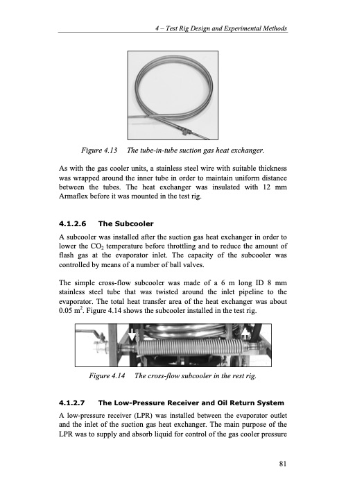
4 – Test Rig Design and Experimental Methods Figure 4.13 The tube-in-tube suction gas heat exchanger. As with the gas cooler units, a stainless steel wire with suitable thickness was wrapped around the inner tube in order to maintain uniform distance between the tubes. The heat exchanger was insulated with 12 mm Armaflex before it was mounted in the test rig. 4.1.2.6 The Subcooler A subcooler was installed after the suction gas heat exchanger in order to lower the CO2 temperature before throttling and to reduce the amount of flash gas at the evaporator inlet. The capacity of the subcooler was controlled by means of a number of ball valves. The simple cross-flow subcooler was made of a 6 m long ID 8 mm stainless steel tube that was twisted around the inlet pipeline to the evaporator. The total heat transfer area of the heat exchanger was about 0.05 m2. Figure 4.14 shows the subcooler installed in the test rig. Figure 4.14 The cross-flow subcooler in the rest rig. 4.1.2.7 The Low-Pressure Receiver and Oil Return System A low-pressure receiver (LPR) was installed between the evaporator outlet and the inlet of the suction gas heat exchanger. The main purpose of the LPR was to supply and absorb liquid for control of the gas cooler pressure 81PDF Image | Residential CO2 Heat Pump System for Combined
PDF Search Title:
Residential CO2 Heat Pump System for CombinedOriginal File Name Searched:
20559406.pdfDIY PDF Search: Google It | Yahoo | Bing
CO2 Organic Rankine Cycle Experimenter Platform The supercritical CO2 phase change system is both a heat pump and organic rankine cycle which can be used for those purposes and as a supercritical extractor for advanced subcritical and supercritical extraction technology. Uses include producing nanoparticles, precious metal CO2 extraction, lithium battery recycling, and other applications... More Info
Heat Pumps CO2 ORC Heat Pump System Platform More Info
| CONTACT TEL: 608-238-6001 Email: greg@infinityturbine.com | RSS | AMP |