PDF Publication Title:
Text from PDF Page: 005
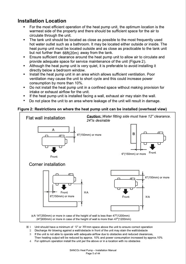
Installation location of the heat pump unit, the optimum location is the Installation location InstalFloarttihoenmloLosotcecafafticitioieonnt operation For the most efficient operation of the heat pump unit, the optimum location is the warmest side of the property and there should be sufficient space for the air to For the most efficient operation of the heat pump unit, the optimum location is the warmest side of the property and there should be sufficient space for the air to circulate through the unit. warmest side of the property and there should be sufficient space for the air to circulate through the unit. The tank unit should be located as close as possible to the most frequently used circulate through the unit. The tank unit should be located as close as possible to the most frequently used hot water outlet such as a bathroom. It may be located either outside or inside. The The tank unit should be located as close as possible to the most frequently used hot water outlet such as a bathroom. It may be located either outside or inside. The heat pump unit must be located outside and as close as practicable to the tank unit hot water outlet such as a bathroom. It may be located either outside or inside. The heat pump unit must be located outside and as close as practicable to the tank unit but not further than 50ft (15m) away from the tank. heat pump unit must be located outside and as close as practicable to the tank unit but not further than 50ft (15m) away from the tank. Ensure sufficient cle ound the heat pump unit to allow air to circulate and arance ar but not further than away from the tank. 50ft (15m) 66ft(20m) Ensure sufficient clearance around the heat pump unit to allow air to circulate and provide adequate space for service maintenance of the unit (Figure 3). Ensure sufficient clearance around the heat pump unit to allow air to circulate and provide adequate space for service maintenance of the unit (Figure 3). Although the heat pump unit is very quiet, it is preferable to avoid installing it provide adequate space for service maintenance of the unit (Figure 23). Although the heat pump unit is very quiet, it is preferable to avoid installing it directly below a bedroom window. Although the heat pump unit is very quiet, it is preferable to avoid installing it directly below a bedroom window. Install the heat pump unit in an area which allows sufficient ventilation. Poor directly below a bedroom window. Install the heat pump unit in an area which allows sufficient ventilation. Poor ventilation may cause the unit to short cycle and this could increase power Install the heat pump unit in an area which allows sufficient ventilation. Poor ventilation may cause the unit to short cycle and this could increase power consumption by more than 10%. ventilation may cause the unit to short cycle and this could increase power consumption by more than 10%. Do not install the heat pump unit in a confined space without making provision for consumption by more than 10%. Do not install the heat pump unit in a confined space without making provision for intake or exhaust airflow for the unit. Do not install the heat pump unit in a confined space without making provision for intake or exhaust airflow for the unit. If the heat pump unit is installed facing a wall, exhaust air may stain the wall. intake or exhaust airflow for the unit. If the heat pump unit is installed facing a wall, exhaust air may stain the wall. If the heat pump unit is installed facing a wall, exhaust air may stain the wall. Do not place the unit to an area where leakage of the unit will result in damage. Figure 3: Restrictions on where the heat pump unit can be installed (overhead view) Figure 23: Restrictions on where the heat pump unit can be installed (overhead view) Figure 3: Restrictions on where the heat pump unit can be installed (overhead view) Flat wall installation Flat wall installation Caution: Water fitting side must have 12” clearance. Flat wall installation Caution: Water fitting side must have 12” clearance. 24”is desirable Caution: Water fitting side must have 12” clearance. 24”is desirable 24”is desirable >6” �� ����� ��������� >6” ���� ���������� ������������������ ����� Corner installation Corner inst ����� ” ” ����� ����� ���������� ����� ���������� >66′′(”1�5�0�m�m��)�or��m��o��r�e�� Corner installation allation 6>′′6(”15��0m� �m � � � > > 6 6 � � � � � � � � � � � � � � � � � � � � � � � � � � > > ����� ��������� � � ����� � � �) r � �o ����� >6” �� ����� ��������� � � 8 8 ” ” o o r r � � � � � m� � �o�r�e� � � � ※A 14′′(350mm) or more in case of the height of wall is less than 47′′(1200mm) 24′′(600mm) or more in case of the height of wall is more than 47′′(1200mm) >12” or ※A ����� ��������� >12” or >66”′′�(1�5�0�m��m�)�o��r�m��o��re� >6” �� ����� ��������� >6” ���� ���������� ������������������ 6′′(150mm) or more ����� ��������� >6” �� >6” �� > > ����� ��������� � � 6 6 ” ” � � � � � � � � � � � � � � � � � � � � � � � > > ����� ��������� 1 1 2 2 ” ” o o r r ����� ����� � � � � � � � � � � ※A >8” or ����� ��������� >8” or � � � � � � � � � � � � � � � � � � � � � � � � � � � � � � � � � � � � � � � � � � � � � � � � � � � � � � � � � � � � ※1 Unit should have a minimum of 18” or 500mm space above the unit to ensure correct operation ※12 UDnisicthsahrogueldAhirabvleowaimnginaimgauimnsotfa1w8a”lol/orb5s0t0amclme inspfarocnetaobfothveuthneitumnaitytosteaninsuthrecwoarlrle/ocbtsotpaeclreation ※1 Unit should have a minimum of 182”′′ or 5300mm space above the unit to ensure correct operation 23 DIf itshcehaurngiteisAnirobtlaowbliengtoaogpaeinrasteawitahll/aodbesqtaucalteinairffrlonwt odfutehetouonbitsmtaacylestaindthredwucaell/dobclsetarcalences, 2 Discharge Air blowing against a wall/obstacle in front of the unit may stain the wall/obstacle 3 TIfhtheen uhneiattiisngnotuatpbulet wtoillobperraetdeuwceithd abdyeaqpupartoex.a1ir0flo%wadnudeptowoebrsctaocnlseusmapntdiornedinucredasceledabraynacpepsr,ox.10% 3 If the unit is not able to operate with adequate airflow due to obstacles and reduced clearances, 4 TFhoernophteimautinmgopuetprauttiownililnbsetarleldthueceudnibtypearptphreoxa.b1o0v%e oarnidnpaolowcearticoonnwsuitmhpntoioonbisntcarcelaesedbyapprox.10% Then heating output will be reduced by approx. 10% and power consumption increased by approx.10% 4 For optimum operation install the unit per the above or in a location with no obstacles 4 For optimum operation install the unit per the above or in a location with no obstacles Sanden Heat Pump – Installation Manual Sanden Heat PPuamgpe –5 Ionfs4ta0llation Manual Sanden Heat Pump – Installation Manual Page 5 of 40 SANCO2 Heat Pump – Installation Manual Page 5 of 40 Page 5 of 44PDF Image | SANCO2 Heat Pump Water Heater R744
PDF Search Title:
SANCO2 Heat Pump Water Heater R744Original File Name Searched:
Installation_Manual_SANCO2.pdfDIY PDF Search: Google It | Yahoo | Bing
CO2 Organic Rankine Cycle Experimenter Platform The supercritical CO2 phase change system is both a heat pump and organic rankine cycle which can be used for those purposes and as a supercritical extractor for advanced subcritical and supercritical extraction technology. Uses include producing nanoparticles, precious metal CO2 extraction, lithium battery recycling, and other applications... More Info
Heat Pumps CO2 ORC Heat Pump System Platform More Info
| CONTACT TEL: 608-238-6001 Email: greg@infinityturbine.com | RSS | AMP |