PDF Publication Title:
Text from PDF Page: 015
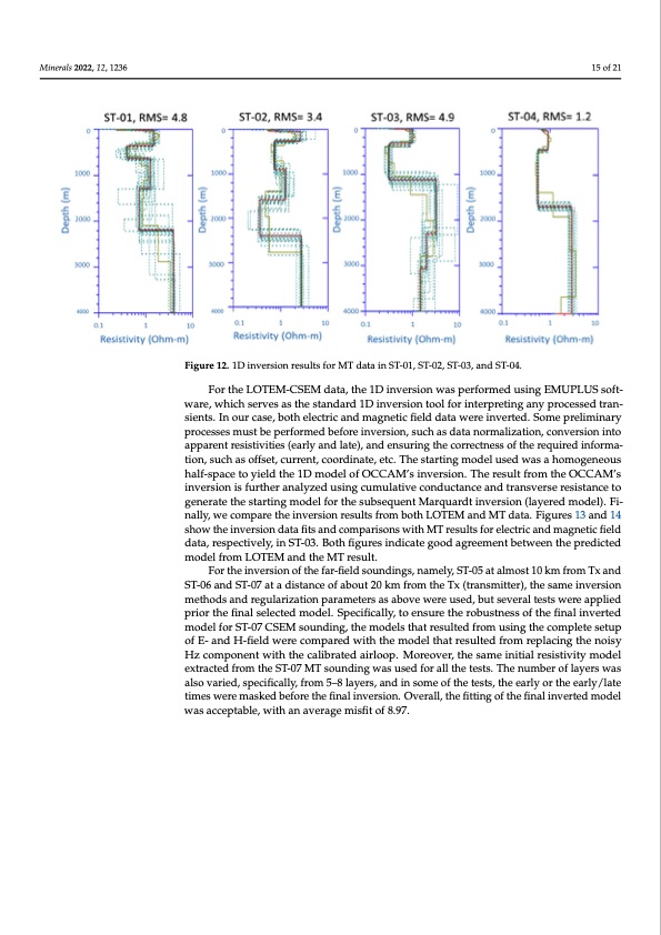
Minerals 2022, 12, x FOR PEER REVIEW 15 of 21 Minerals 2022, 12, 1236 15 of 21 Figure 12.. 1D iinversiion results for MT data in ST-01, ST-02, ST-03, and ST-04.. For the LOTEM-CSEM data, the 1D inversion was performed using EMUPLUS soft- For the LOTEM-CSEM data, the 1D inversion was performed using EMUPLUS soft- ware, which serves as the standard 1D inversion tool for interpreting any processed tran- ware, which serves as the standard 1D inversion tool for interpreting any processed tran- sients. In our case, both electric and magnetic field data were inverted. Some preliminary sients. In our case, both electric and magnetic field data were inverted. Some preliminary processes must be performed before inversion, such as data normalization, conversion into processes must be performed before inversion, such as data normalization, conversion apparent resistivities (early and late), and ensuring the correctness of the required informa- into apparent resistivities (early and late), and ensuring the correctness of the required tion, such as offset, current, coordinate, etc. The starting model used was a homogeneous information, such as offset, current, coordinate, etc. The starting model used was a homo- half-space to yield the 1D model of OCCAM’s inversion. The result from the OCCAM’s geneous half-space to yield the 1D model of OCCAM’s inversion. The result from the OC- inversion is further analyzed using cumulative conductance and transverse resistance to CAM’s inversion is further analyzed using cumulative conductance and transverse re- generate the starting model for the subsequent Marquardt inversion (layered model). Fi- sistance to generate the starting model for the subsequent Marquardt inversion (layered nally, we compare the inversion results from both LOTEM and MT data. Figures 13 and 14 model). Finally, we compare the inversion results from both LOTEM and MT data. Figures show the inversion data fits and comparisons with MT results for electric and magnetic field 13 and 14 show the inversion data fits and comparisons with MT results for electric and data, respectively, in ST-03. Both figures indicate good agreement between the predicted magnetic field data, respectively, in ST-03. Both figures indicate good agreement between model from LOTEM and the MT result. the predicted model from LOTEM and the MT result. For the inversion of the far-field soundings, namely, ST-05 at almost 10 km from Tx and For the inversion of the far-field soundings, namely, ST-05 at almost 10 km from Tx ST-06 and ST-07 at a distance of about 20 km from the Tx (transmitter), the same inversion and ST-06 and ST-07 at a distance of about 20 km from the Tx (transmitter), the same methods and regularization parameters as above were used, but several tests were applied inversion methods and regularization parameters as above were used, but several tests prior the final selected model. Specifically, to ensure the robustness of the final inverted were applied prior the final selected model. Specifically, to ensure the robustness of the model for ST-07 CSEM sounding, the models that resulted from using the complete setup final inverted model for ST-07 CSEM sounding, the models that resulted from using the of E- and H-field were compared with the model that resulted from replacing the noisy complete setup of E- and H-field were compared with the model that resulted from re- Hz component with the calibrated airloop. Moreover, the same initial resistivity model placing the noisy Hz component with the calibrated airloop. Moreover, the same initial extracted from the ST-07 MT sounding was used for all the tests. The number of layers was resistivity model extracted from the ST-07 MT sounding was used for all the tests. The also varied, specifically, from 5–8 layers, and in some of the tests, the early or the early/late number of layers was also varied, specifically, from 5–8 layers, and in some of the tests, times were masked before the final inversion. Overall, the fitting of the final inverted model the early or the early/late times were masked before the final inversion. Overall, the fitting was acceptable, with an average misfit of 8.97. of the final inverted model was acceptable, with an average misfit of 8.97. After the individual inversion of all the acquired MT/CSEM soundings, the four near the Tx (ST-01–ST-04), the soundings collected along an SW–NE profile, were reprocessed by applying a 2D inversion. For the 2-D inversion of the near field EM soundings, the REBOCC code [47], with the modification from Pedersen and Engels [48] to allow for the inversion of the determinant of the impedance tensor, was used [21]. The average deter- minant of the impedance tensor, Zdet, is given by, Zdet = (ZxxZyy − ZxyZyx)1/2, where Zxx, Zxy, Zyx, and Zyy are the impedance tensor elements [49]. When inverting determi- nant data, the strike determination is less critical than inverting E- and H-polarization data [50]. The possible static shift correction is also more convenient in the case of the rotation- ally invariant determinant data, as no decomposition to the E- and the H-polarizationPDF Image | First High-Power CSEM
PDF Search Title:
First High-Power CSEMOriginal File Name Searched:
minerals-12-01236-v2.pdfDIY PDF Search: Google It | Yahoo | Bing
Product and Development Focus for Infinity Turbine
ORC Waste Heat Turbine and ORC System Build Plans: All turbine plans are $10,000 each. This allows you to build a system and then consider licensing for production after you have completed and tested a unit.Redox Flow Battery Technology: With the advent of the new USA tax credits for producing and selling batteries ($35/kW) we are focussing on a simple flow battery using shipping containers as the modular electrolyte storage units with tax credits up to $140,000 per system. Our main focus is on the salt battery. This battery can be used for both thermal and electrical storage applications. We call it the Cogeneration Battery or Cogen Battery. One project is converting salt (brine) based water conditioners to simultaneously produce power. In addition, there are many opportunities to extract Lithium from brine (salt lakes, groundwater, and producer water).Salt water or brine are huge sources for lithium. Most of the worlds lithium is acquired from a brine source. It's even in seawater in a low concentration. Brine is also a byproduct of huge powerplants, which can now use that as an electrolyte and a huge flow battery (which allows storage at the source).We welcome any business and equipment inquiries, as well as licensing our turbines for manufacturing.| CONTACT TEL: 608-238-6001 Email: greg@infinityturbine.com | RSS | AMP |